Austin Area Revit User Group Meeting
Will you be in Austin on Tuesday, May 8th, 2018? Come listen to Xavier Loayza talk about “BIM 360 Design – Transitioning to the New Revit Cloud Worksharing”
[···]
Will you be in Austin on Tuesday, May 8th, 2018? Come listen to Xavier Loayza talk about “BIM 360 Design – Transitioning to the New Revit Cloud Worksharing”
[···]
Typically when people hear the word Navisworks they automatically think of clash detection… Is that all that Navisworks is really capable of? The answer is No.
There are a variety of things possible through Navisworks. For instance, creating a simulation. It is one of the most beneficial ways to get organized out in the field, and cut down on dead time.
Simulation
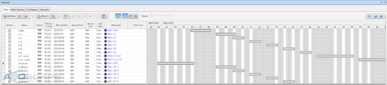
This process consists of a schedule with start dates, end dates, and phasing. With the simulation capabilities, it is possible to simulate the order and process of how things will occur out on site. Here’s a glimpse of what the schedule looks like.
There are multiple ways to schedule things out. The first way would be within the program itself. To start scheduling components, they will have to be apart of a set.
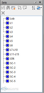
(A set in Navisworks is a group of selected components.)
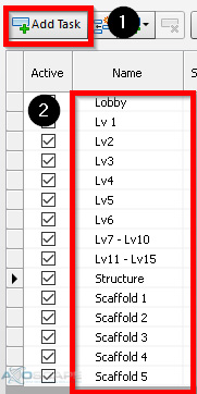
Once all the sets are formed, then the task will need to be created and named accordingly. The name of the task will appear on the simulation as the video progresses.
There are settings to control the content that is visible on the side of the screen.
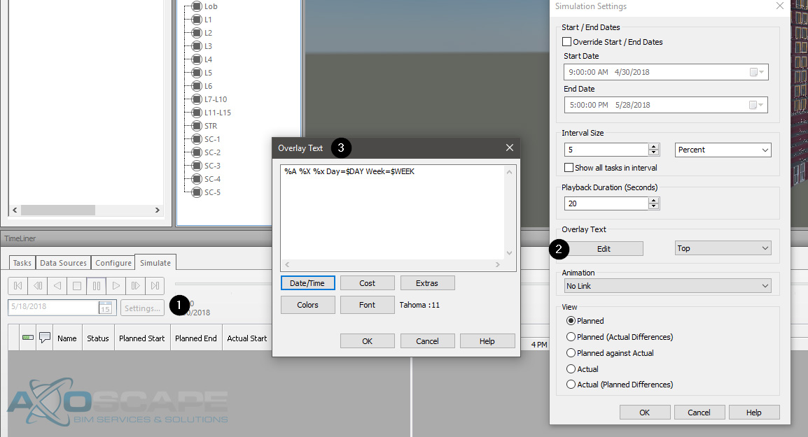
Within here, the dates/ times can be adjusted to display actual dates/ time (May 2, 2018, May 3, 2018, etc) if needed, or it could be a generic date etc (day 1, day 2, day 3…) There are plenty of other factors that can be included.
Once the task is created, the next step will be to attach the sets to the corresponding task. To attach sets to a specific task, right click on the “attached” column and go to the “set” that needs to occur at that task.
Lastly, set all the attachments to a “task”, and then add a start and end date to each one.
An alternative way to set up a schedule is to import a “csv” file (comma-separated values). This process involves more typing, BUT it’s a lot faster in the long run. The sets will have to be configured beforehand in order for this to work. Only critical step in this process is to have the nomenclature under the “Attached” column match the “sets” nomenclature, or else the “Attached” column will be empty.
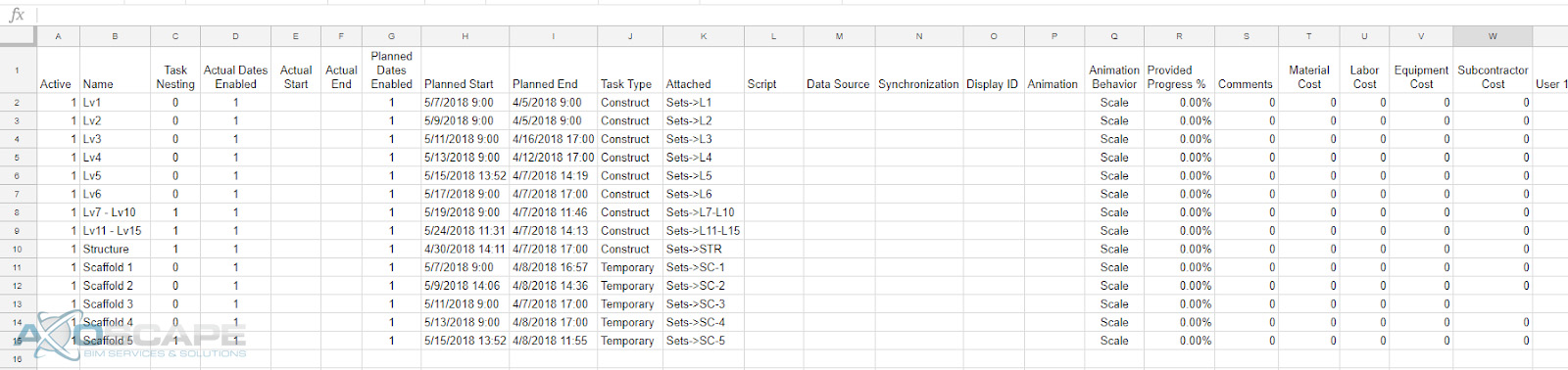
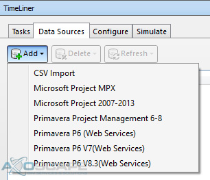
The chart above represents the layout of how it’s supposed to be laid out before importing into the Navisworks file. To import the csv or any other excel file format, go to “Data Sources” > click “Add” > select the file format that will be imported.
Once imported, it should populate the schedule within Navisworks. The only downside to importing a csv or any excel format is that it only populates Monday-Friday. Saturday and Sunday will remain empty and when this is exported, there will be a long pause in between Friday and Monday. Now if this isn’t a problem then this method would be ideal but if not, then there’s a little manual work to be done.
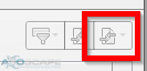
To export the simulation, click on the “Simulate” tab and click on a box with two arrows pointing to the center.
This will bring up a window with some export options. This portion is more of a personal preference and how the simulation will be used.
Background
On April 9th, Autodesk released the next generation of cloud worksharing aiming to replace what we currently know as Collaboration for Revit (C4R) and rebranding it as BIM 360 Design. On the technical side, Autodesk argues their services change in order to provide a better experience on Forge based platforms, however, there are some licensing differences as well. Without getting too much into the financials, this tutorial series intends to review and show new workflows using this next generation of tools that we have inherited. This new BIM 360 Docs environment is definitely more powerful, but it will require more set up time for the permission portion until your team finds the right way to share data within your projects.
“Our ability to adapt is amazing. Our ability to change isn’t quite as spectacular. “ —Lisa Lutz
The facts presented here are based on the limited time we had for testing since the release date. Please, let me know if you find any discrepancies. Let’s start!
Introduction
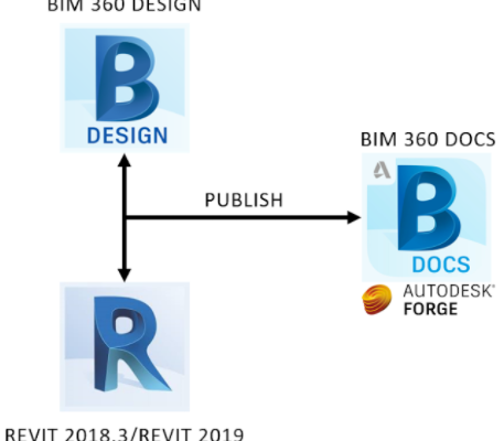
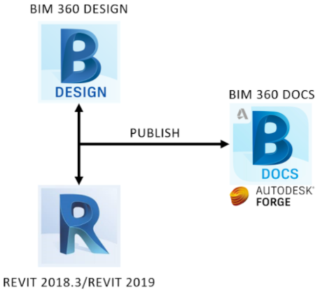
The following graph represents the BIM 360 Team vs the BIM 360 Docs processes.
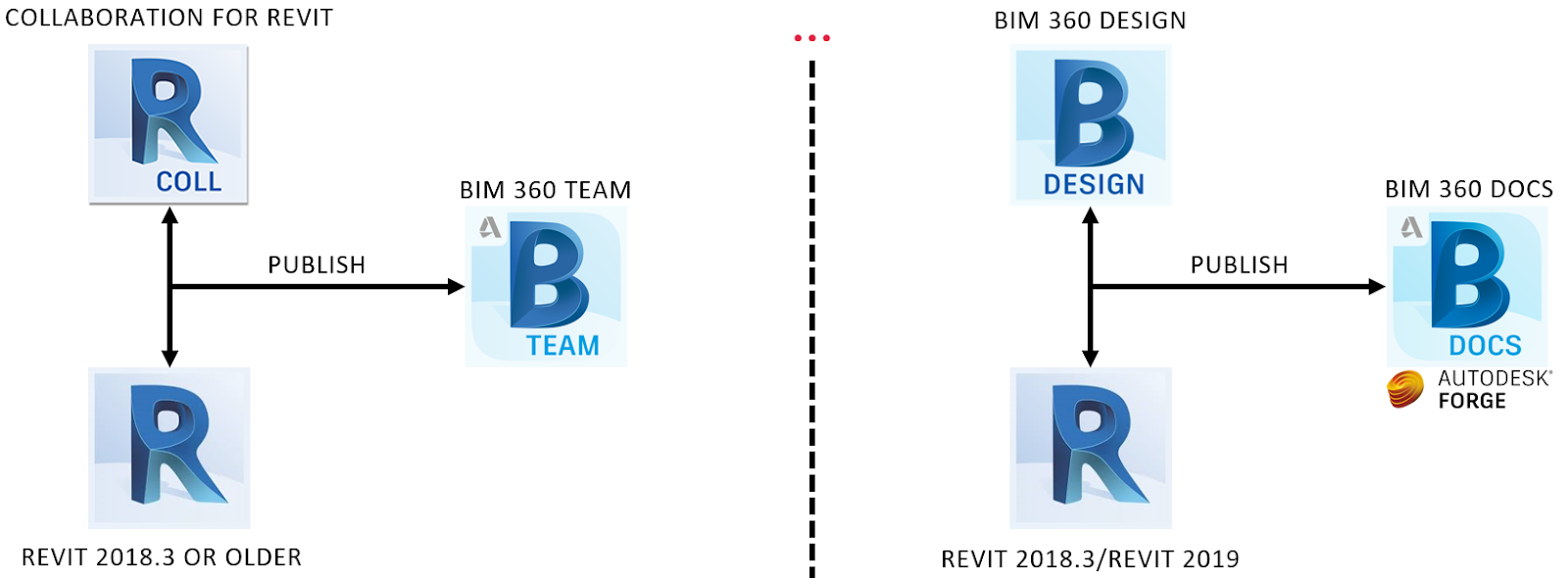
Notice Revit 2018.3 is the only version that works with the old and new cloud worksharing platform (C4R and BIM 360 Design). The user still has to hit the publish button in order to reflect the latest Revit model changes to BIM 360 Docs (Also, can be done from Docs). After diving into Revit 2019, there is no going back to C4R. Autodesk will continue to provide support for BIM 360 Team. However, Autodesk will do its best to convince your team to use BIM 360 Docs for your next project. With that being said, no migration tool is going to be provided to transfer projects from BIM 360 Team to BIM 360 Docs.
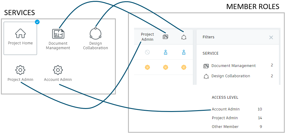
An exciting feature of the new platform are permissions and access levels for company hubs and project members. In addition to this, in the Design Collaboration module, Project Admins can create teams (Services > Design Collaboration) to manage cloud models, allowing another level of control while also avoiding interference with other teams. For this reason, the workflows presented on this tutorial address not only how to get started with a cloud project, but also how to properly add users using multiple methods to filter access levels while facilitating the data and communication flow.
The image below maps the services activated in a project and members’ access/roles assigned.
The Workflow on Video
Disclaimer: If you hear me saying “BIM 360 Ducks”, I mean “BIM 360 Docs” 🙂

How do I create a project for the new cloud worksharing platform – BIM 360 Design?
How can I add users/members to my BIM 360 Docs Project?
| Problem: I created a project, but I cannot see its project folder though Revit > Open
Solution: Users will not be able to see the project folder in Revit until the first Revit model has collaborated to the cloud (BIM 360 Document Management). See video below. |
How can I collaborate the first Revit Model and assign members to a Design Collaboration Team?
| Problem: I created a Design Collaboration Team, how can I add members to it?
Solution: (Project Admin > Services > Design Collaboration) Click on the checkbox of the Team you want. Next, click on Manage team members. Finally, Add them and assign permissions. See video below. |
A user is assigned to a Team to collaborate a model to the cloud.
| Problem: A Design Collaboration Team member collaborated a revit model, but nothing has been shared from other teams so, this user can bring context to his/her model
Solution: In order to have access to other Team’s models, they have to create a Package using the Design Collaboration module and share it with other Teams. See video below. |
| Problem: A Design Collaboration Team member can open and edit Revit files from its own Design Collaboration Team, but I cannot share packages with other Design Collaboration Teams
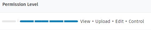
Solution: This user probably does not have the required permission level. Make sure the permission level (Project Admin > Services > Design Collaboration) is set to View-Edit-Share |
The “Reuse” command uses the document version of the package we plan to reuse.
The create “New Package” command uses the last version that has been published from Revit or Updated to Latest from Design Collaboration
Decide what shared Revit files link to your Revit Model using the “Consume” command
Notice that this workflow also works with Automatically created folders (from Design Collaboration Teams)
Also, the permission level showed below provides almost Admin level power just for that folder that is assigned to.
Big thanks to the person from Autodesk that put the document under references together and to Ignacio Rodriguez and Tony Trinh who helped me with content and video editing. Finally, shoutout to Katie Watton, who is creating more in-depth and relevant learning content about this topic for the CADLearning team.
References
Facts
Most owners don’t build enough buildings to fully understand the process, what all is involved, how long it actually takes, what could go wrong, and the ‘actual’ costs.
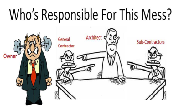
Cost overruns are so common that contingency fees average upwards of 5%. Some of these have to do with changes however most are due to:
Therefore, there will be delays due to miscommunication between owners and architects, architects and contractors, and contractors and owners.
So what does the ideal project look like?
Crystal clear communication between all parties:
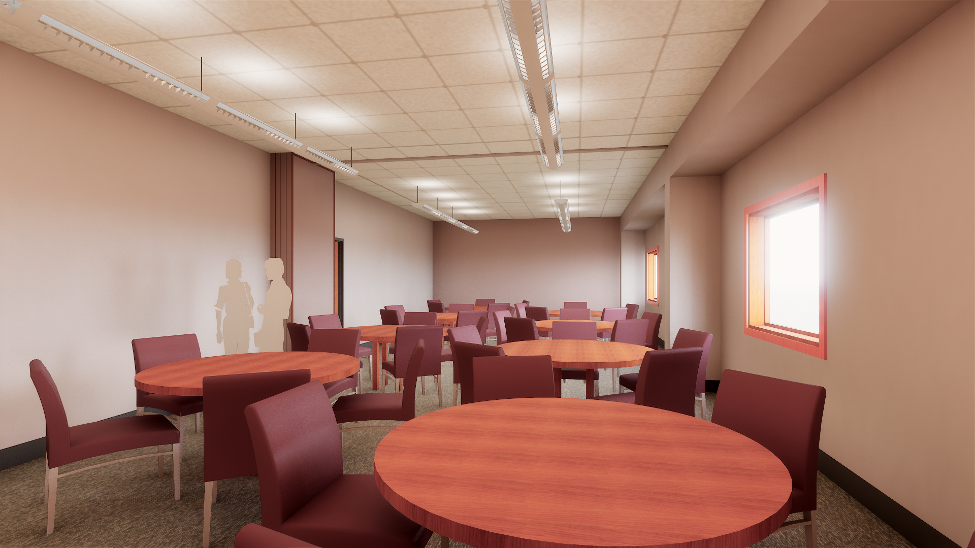
The project schedule is realistic as all parties have a hand in creating it and have signed off on dates for deliverables. Also, only the necessary materials are used as waste is kept to a minimum along with a clean and organized job site.
How we get there
Owners should select their team as early as possible so that communication may begin right away. They could create a virtual mock-up of the project and make this an expectation from the beginning. Besides, a plan should be devised that includes schedules, execution, and development of objects in the virtual model.
A virtual model allows for:
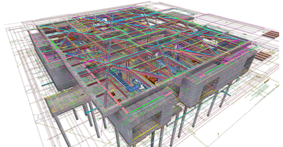
Hold collaboration meetings using the models as a tool, and have a cloud-based workspace (not just repository) so:
Prefab based off of model components = higher quality, less waste, and controlled environments means less dependency on weather and more on-time completion.
Some people might have this question: Why not just make the architect or general contractors responsible for this?
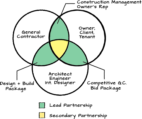
Because they would not work well together. They have good intentions; however, let’s take a look at the differences:
Architects will focus on design intent. They charge by hours. They are concerned mainly with the design schedule.
Whereas, contractors will focus on buildability which is the easier, the better. They have fixed budget. They are concerned mainly with the construction schedule.
What is needed?
A third-party ‘referee’ that is impartial, that understands and has experience with all parties:
Someone who can facilitate the technology that makes all the communication and collaboration (not to mention dealing with all the different file types and software) possible.
Axoscape consists of experienced architects, engineers, and construction detailers and we will help you:
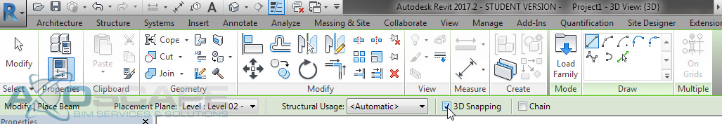
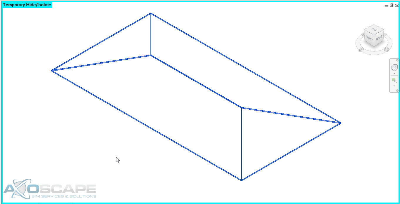
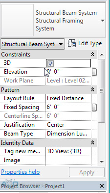
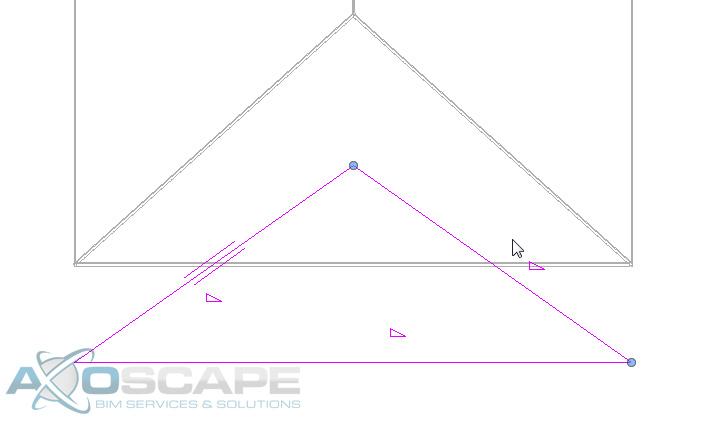
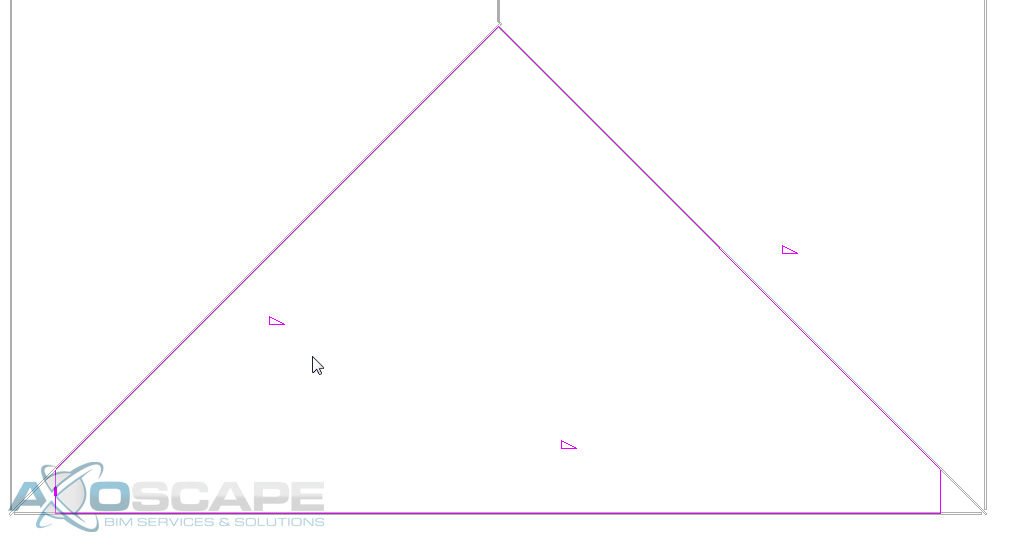
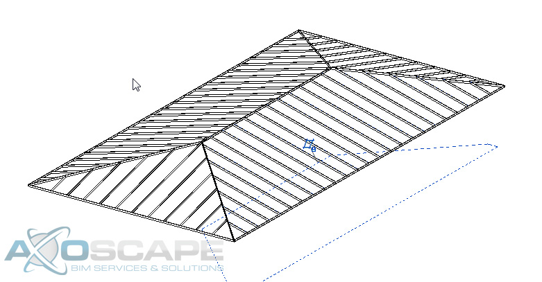
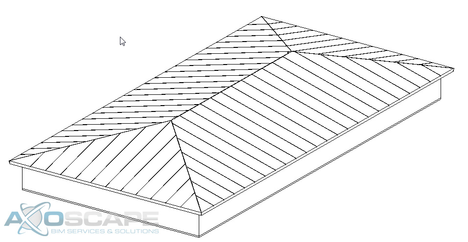
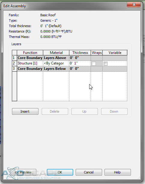
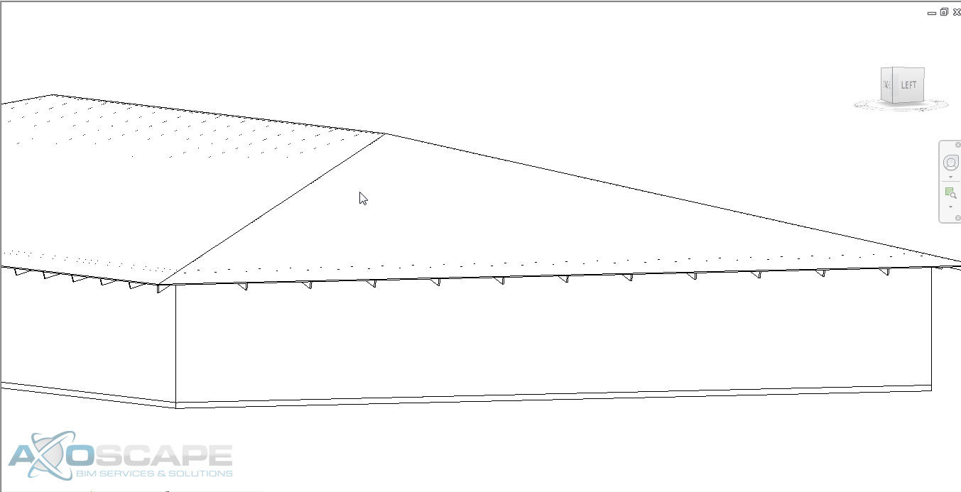
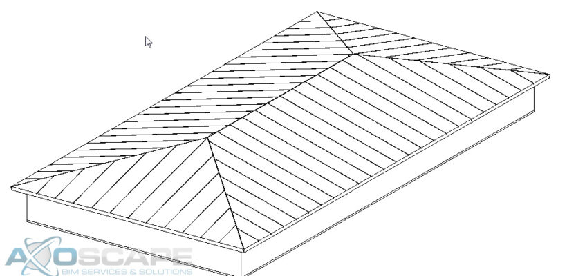
When creating rafter tails with a beam system, it can be difficult. Also, if you need to have a custom rafter tail end, you will need to modify both ends of the beam to your desired design.
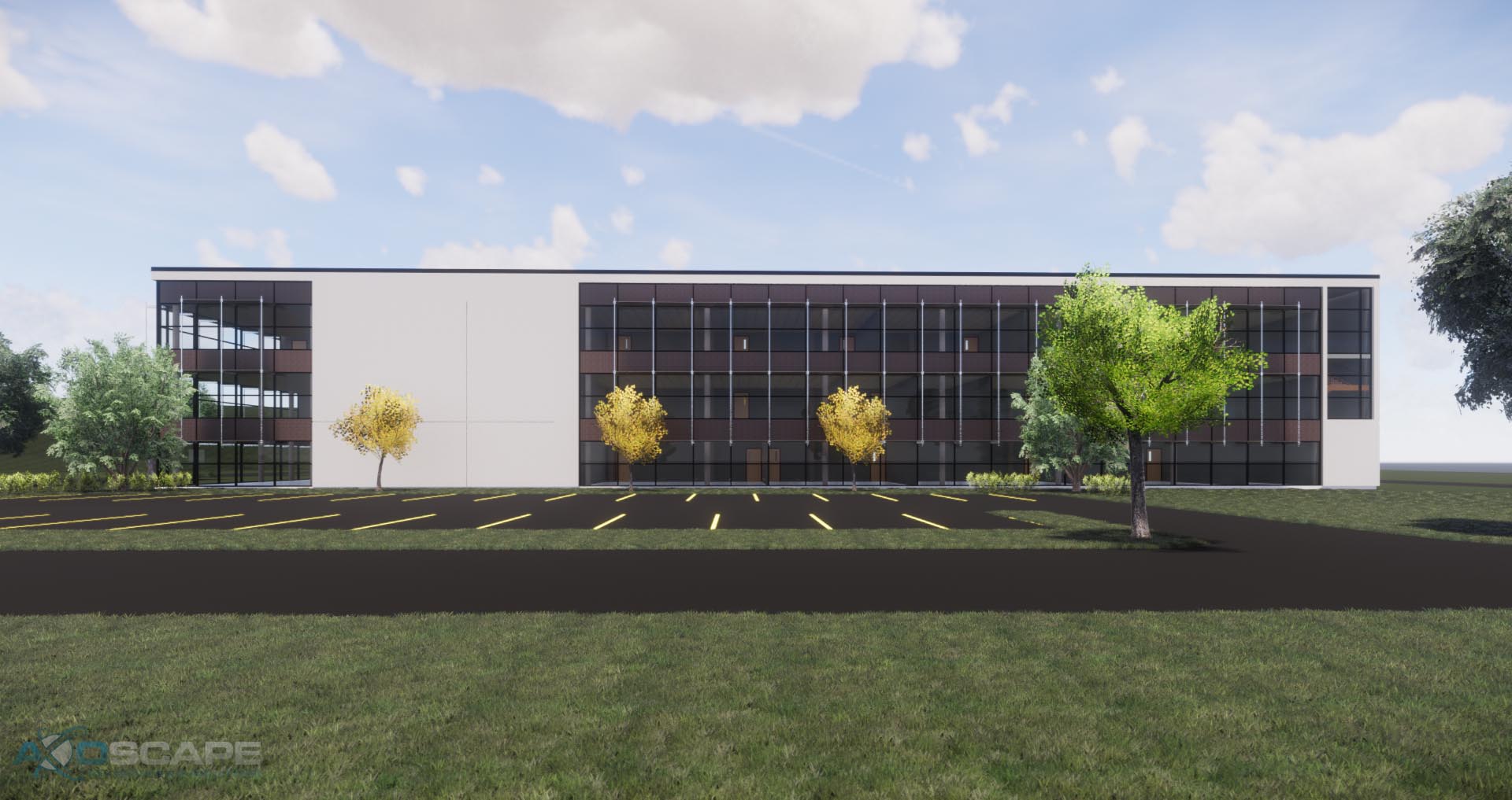
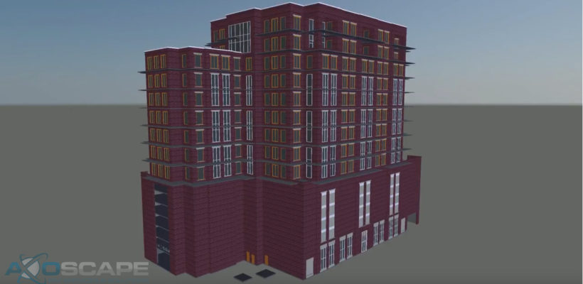
In this guide, we will be covering cameras in Enscape.
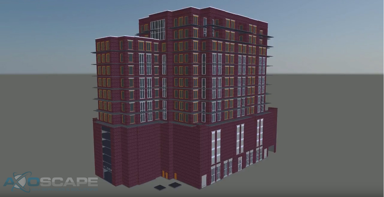
I will be using the 2018 sample Revit building. Once in Enscape, navigate to the spot you want to begin the animation.
Once you have picked the point where you want to begin the animation, tweak the lighting to your liking, frame your scene and press “K” to add a keyframe.
![]()
Don’t worry too much about the angle of the shot or the lighting as those settings can be changed anytime. Right now focus on the path you want the camera to take.
Move to the next point and repeat the above steps to create the different keyframes of the walkthrough.
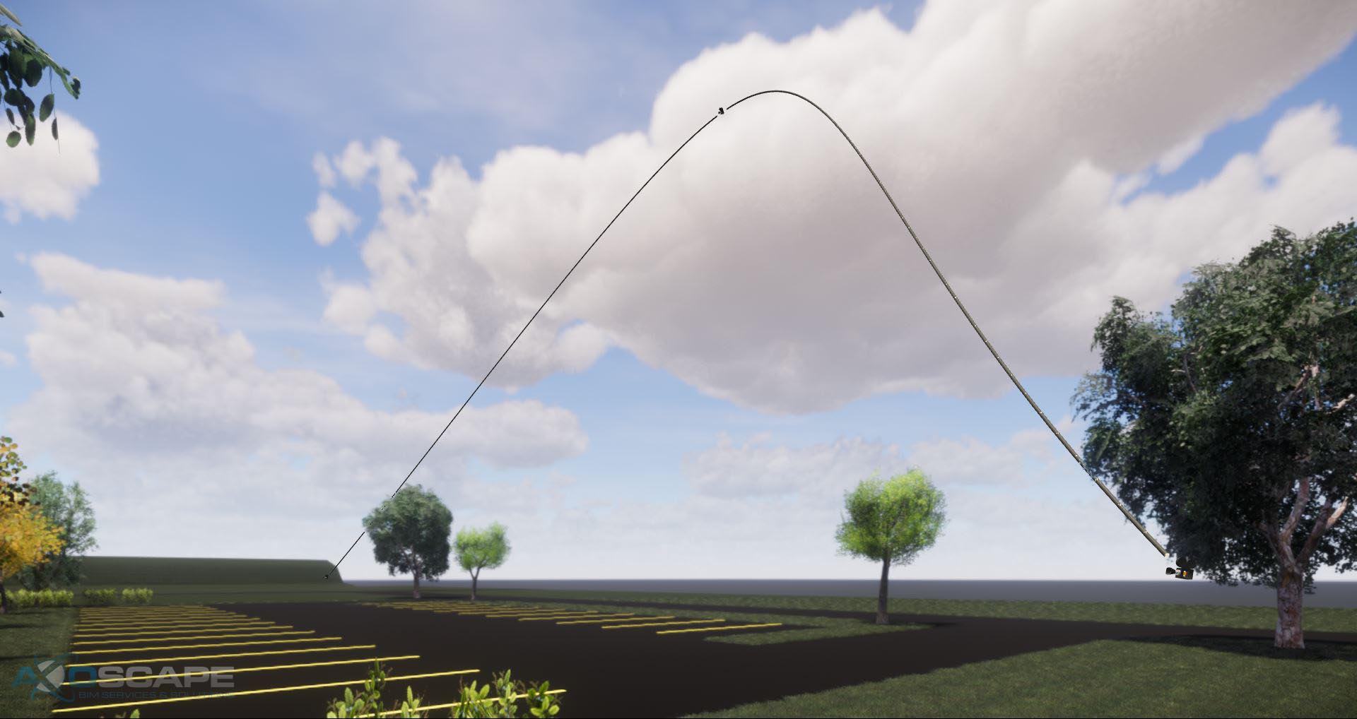
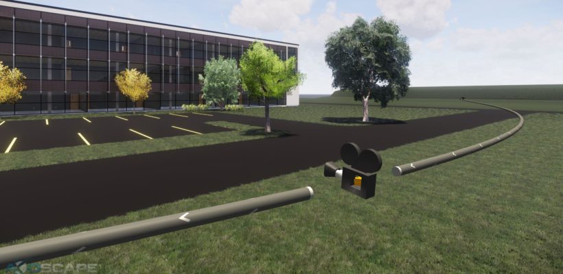
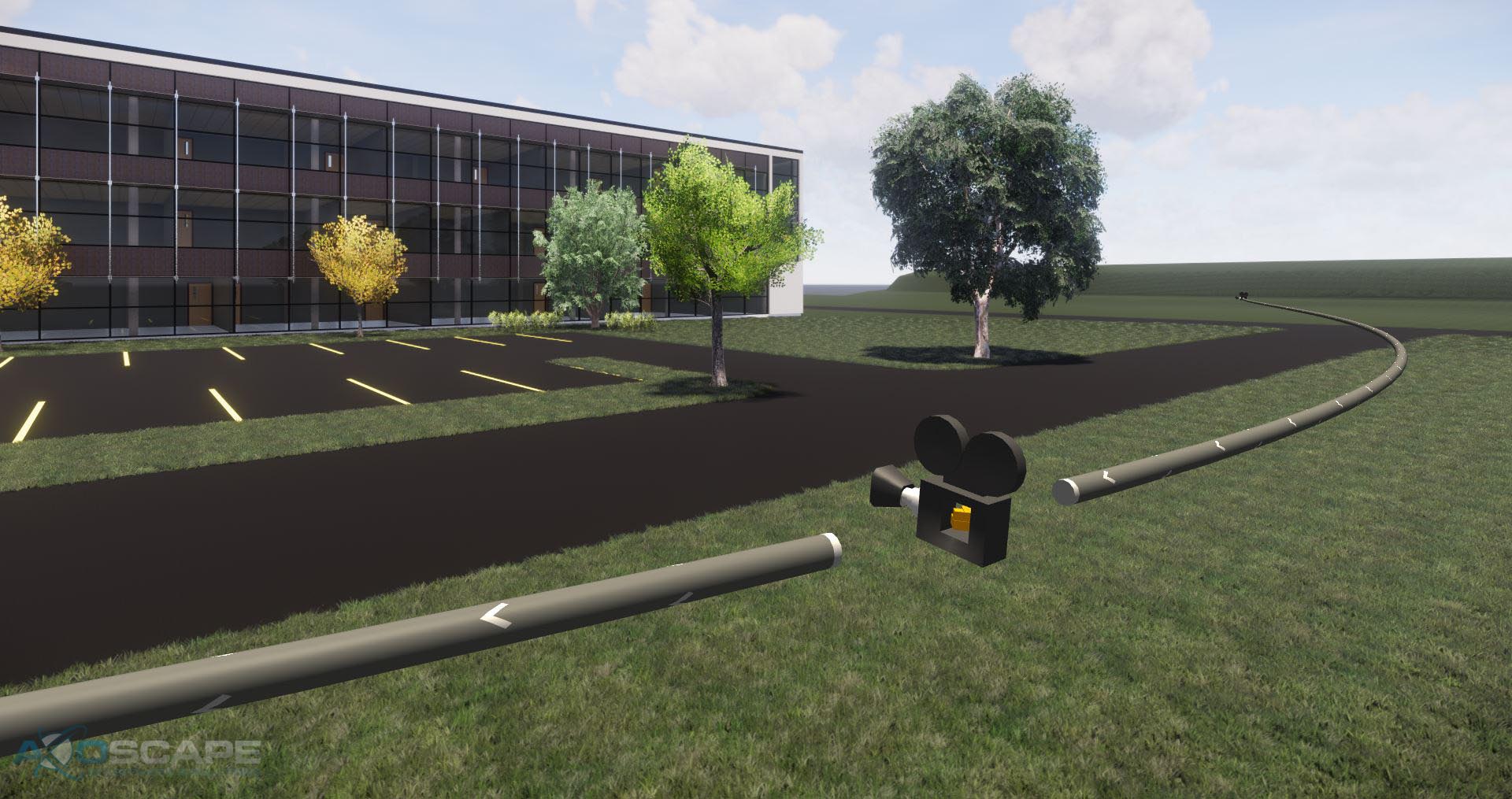
Once you’ve added the keyframes a visual representation of the camera path should appear.

This path is extremely helpful for a couple of reasons. It shows the direction of the camera path, the focal point of the keyframes and is completely interactive.
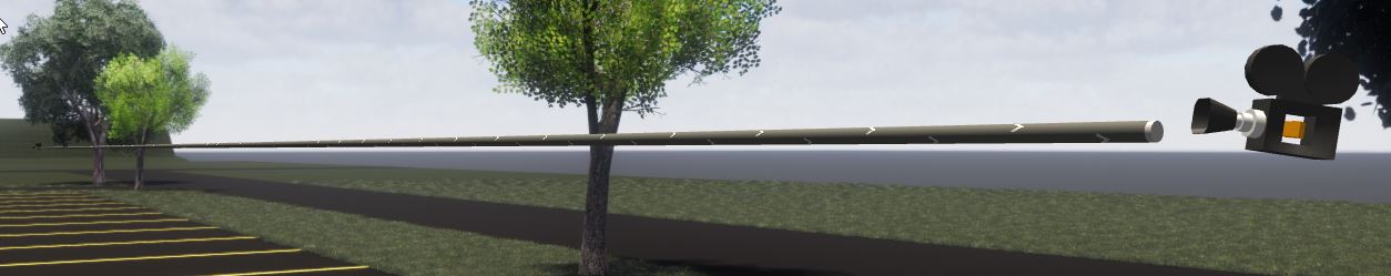
The camera object on the path represents the keyframes and can be edited. Clicking on a camera will bring up the keyframe editor.
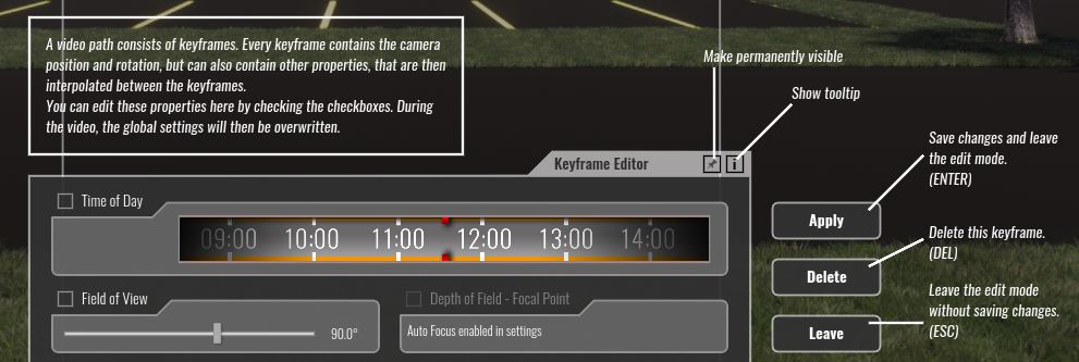
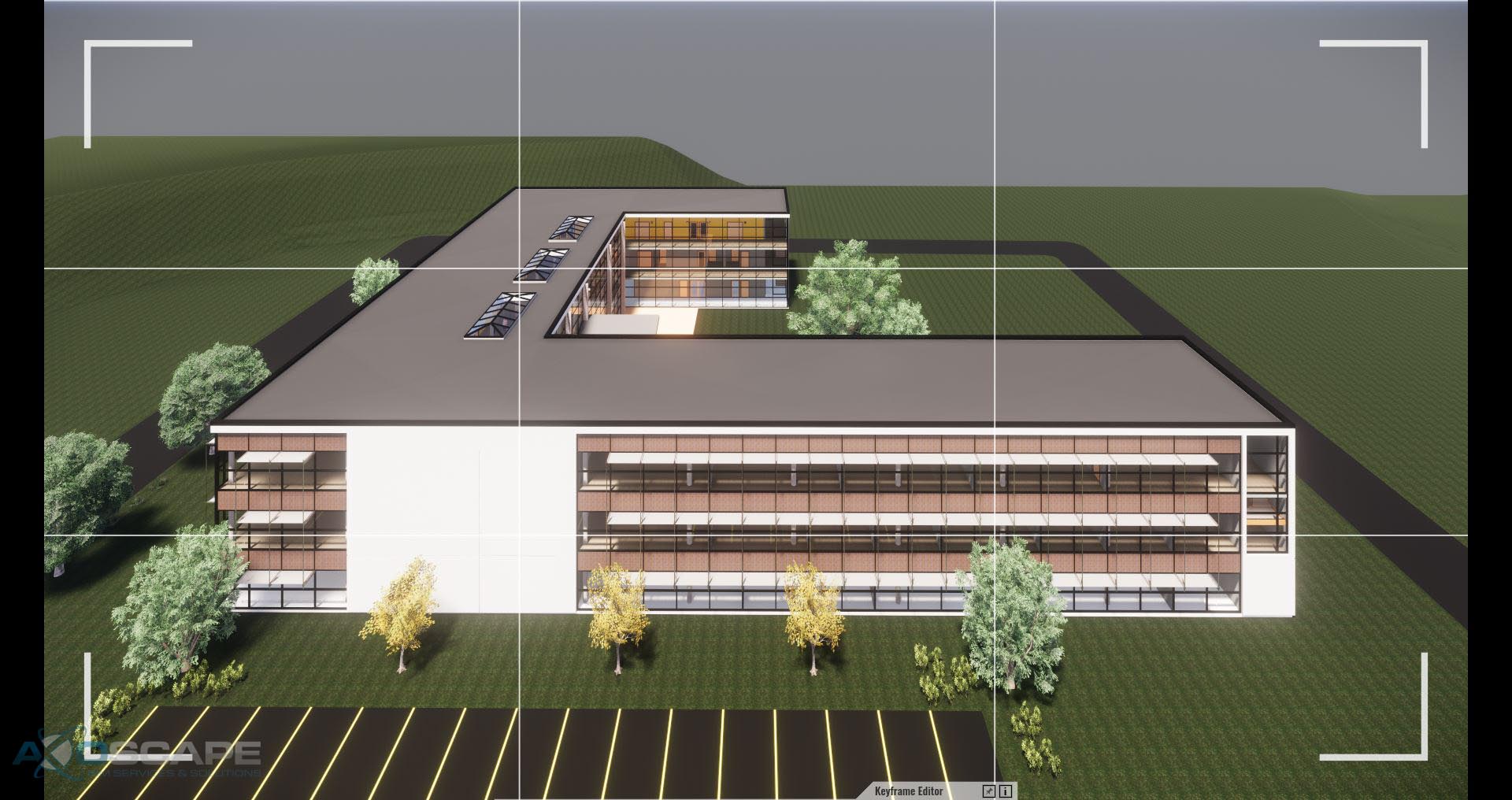
This user interface will let you change all the details within a keyframe. Along with these settings, the rotation of camera and position can also be edited. For example, let’s select the center keyframe and fly the camera above the building. The camera path will adopt this new position and adjust for the change automatically between the three keyframes. Be sure to accept the changes by click on “Apply” to save your changes.
Another useful feature is the ability to delete and add keyframes in an existing path.
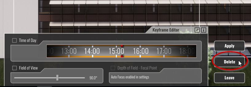
To delete a keyframe select the keyframe you want to be removed and click on delete. This will remove the keyframe from the camera path. To my knowledge, this action is non-reversible.
Adding a keyframe is just as easy, simply hover over any portion of the camera path and click to create a keyframe.
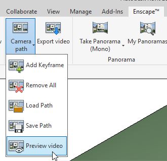
Once all the keyframes have been adjusted and created, test the animation with the preview video command in the Enscape Tab.
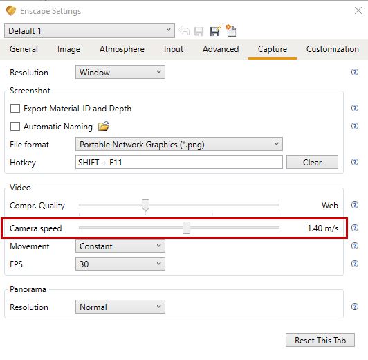
To adjust the speed of the camera go to Enscape settings and adjust the camera speed slider
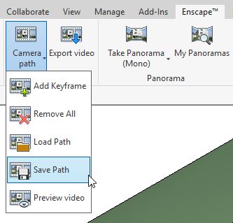
After finalizing all settings, saving the path will export an XML file.
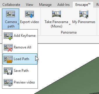
At this point, the path has been created, tweaked, finalized and exported. All that is left to do is to either Export the video or distribute the XML to others to load.
Alternatively, if your computer can handle it, using a screen capture tool to capture the preview video is a great way to get footage for the purposes of finalizing walk through paths. It’ll save a lot of time but it may not give you the quality depending on your needs.
Autodesk released Revit 2018.3 and BIM 360 Design (Rebranded Collaboration for Revit) merging Revit and BIM 360 Docs.
Autodesk is moving away from BIM 360 Team into a Forge based environment. Your current projects will be still hosted in the Team environment for Revit 2018.3 and older versions. Check out the new interface!
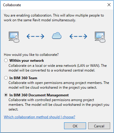
Notice the 3rd option to collaborate files “In BIM 360 Document Management” which will basically sync your Revit project in BIM 360 Design and it will be reflected in BIM 360 Docs.
Railings are probably one of the harder tools to master in Revit. The menus and multiple sub-types of elements can be confusing. Don’t worry, we can handle this one rail at a time. Let’s start!
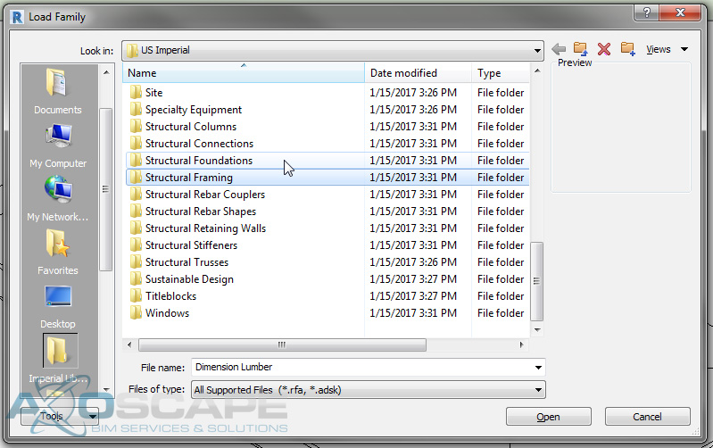
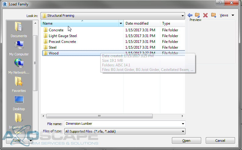
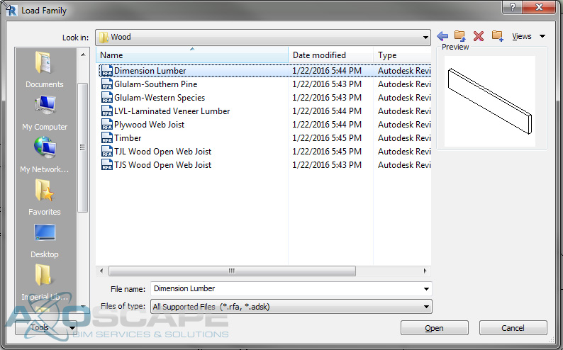
To create a new railing family using the profile Revit Family Profile, go to “File/New/Family” and scroll to Profile-Rail.rft and Open.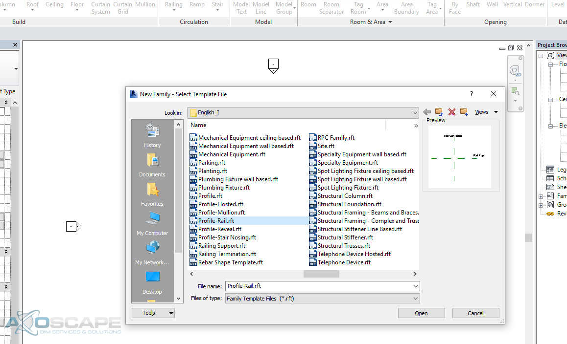
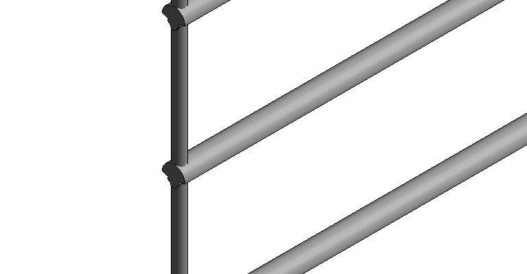
Inside Profile-Rail, you get a Rail Centerline and a Rail Top. You have 2 ref. plans and both are defined origin as marked under properties. Which means the insertion point is at the cross-hair of the two ref. plans.
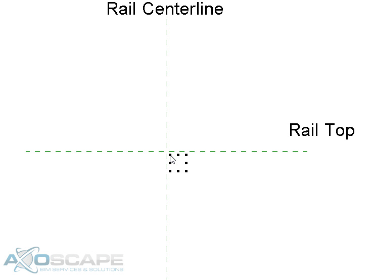
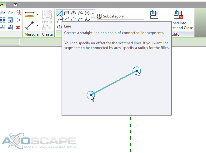
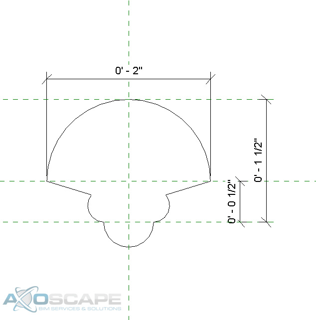
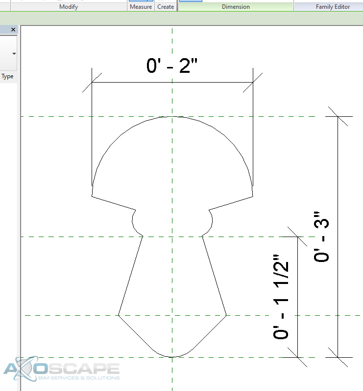
Click the Create tab of the ribbon, line command under detail panel. Draw something simple to represent the rail of choice. Save the rail file family as Custom Profile 1.
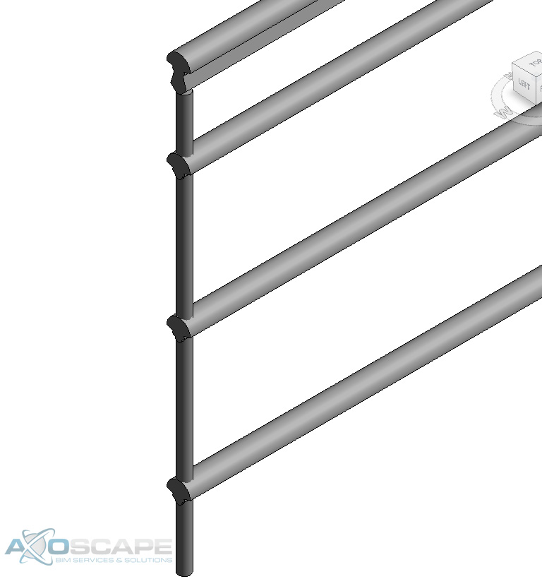
You can change the lower horizontal railing to any shape/size/height you would like to fit the railing profile in your project.
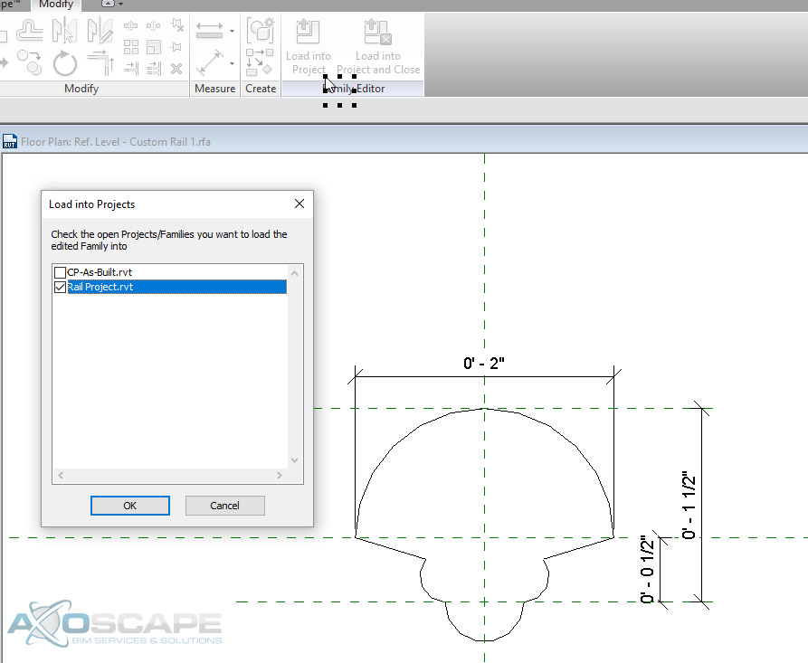
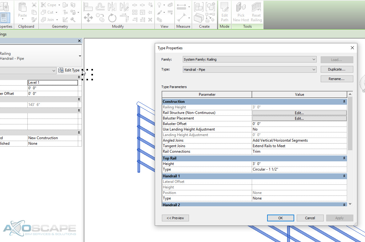
Open the project with the rail you want to alter and load the rail profile into the project.
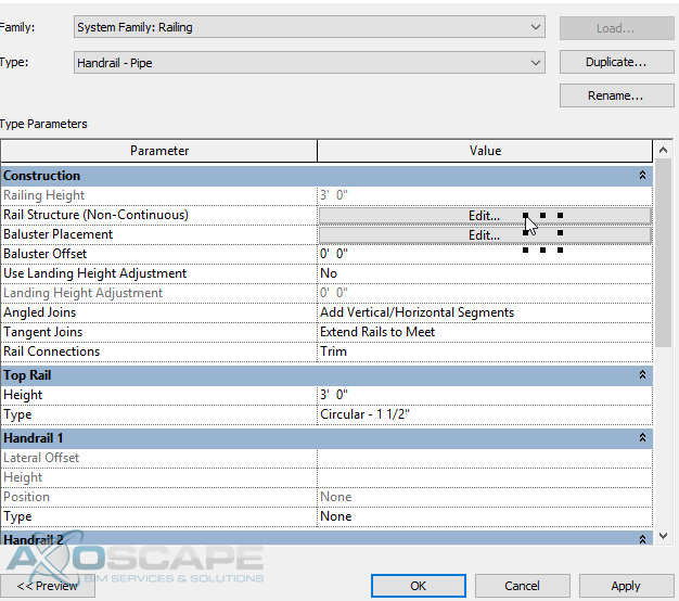
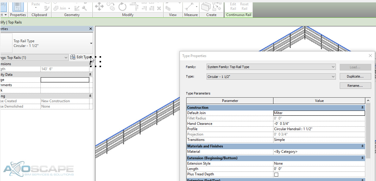
Select the rail and go to the Edit Type. Once the Edit Type window opens, click Edit at Rail Structure (Non-Continuous) to open Edit Rails (Non-Continuous) window. Click the rail you want to change under Profile and you will see the Custom Profile 1 rail is there.
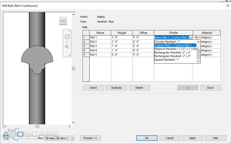
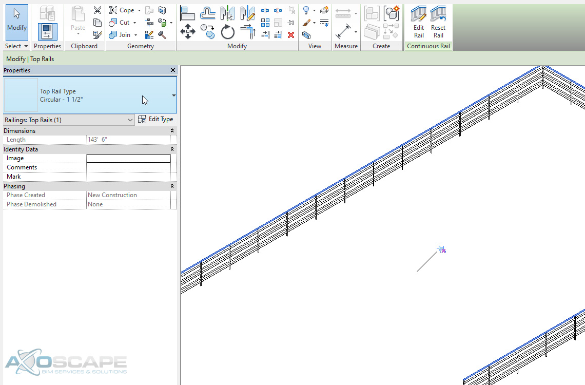
As for the top horizontal railing, you can tab into the top rail. Left click it to select it. You will notice there is a pin feature located on the rail. The reason is that the railing system family has it as a separate object that you have to treat and adjust independently. So, unpin the rail to have access the properties palette under the type selector. Continue by following similar to step 5. Click Profile to access the profile for the top horizontal railing.
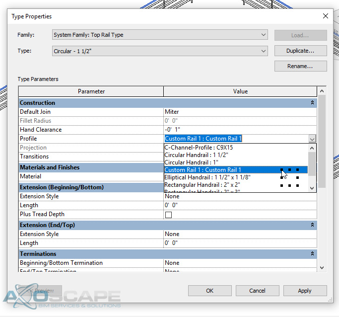
This time, let’s create a Custom Rail 2 family to make it look a little different and load into the project. Click Profile and change the existing railing to Custom Rail 2.
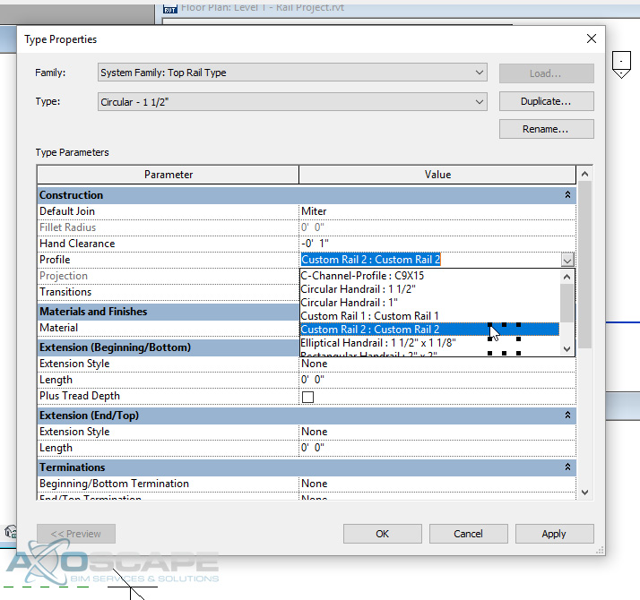
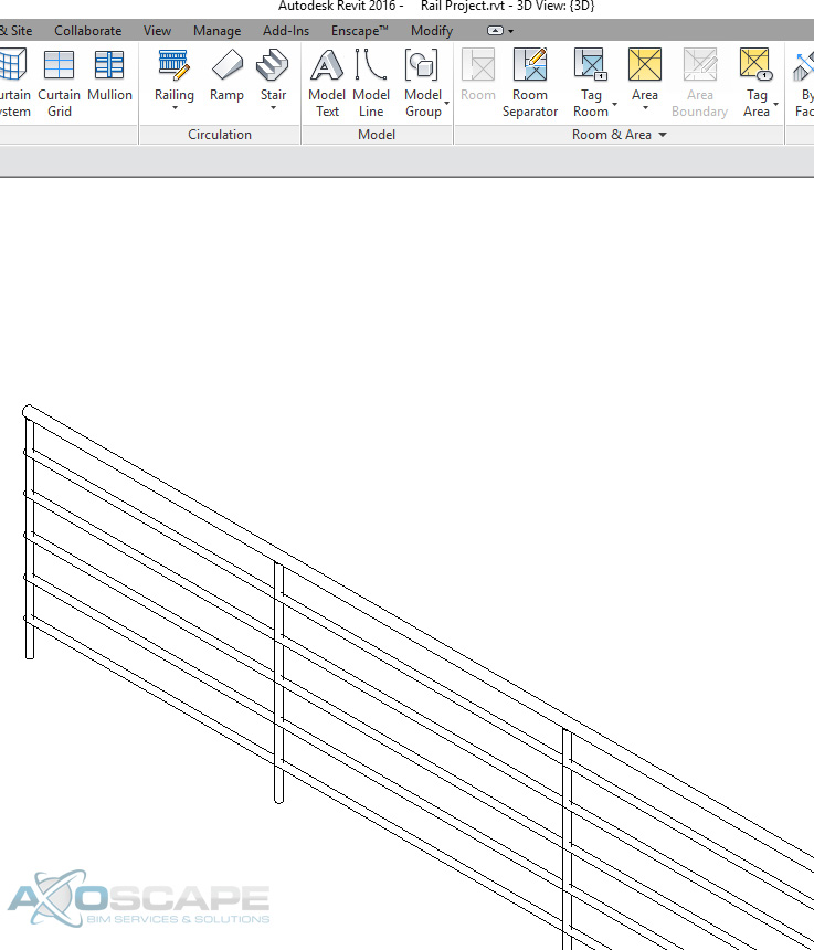
The end result will be what is shown below. You can adjust as you please to make it the way you want it. Play around and just have fun with the design.
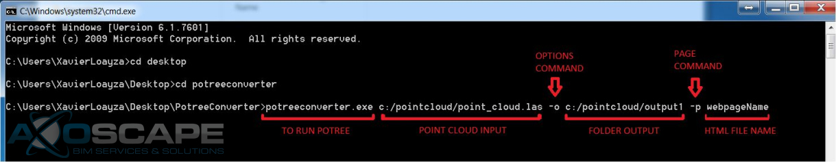
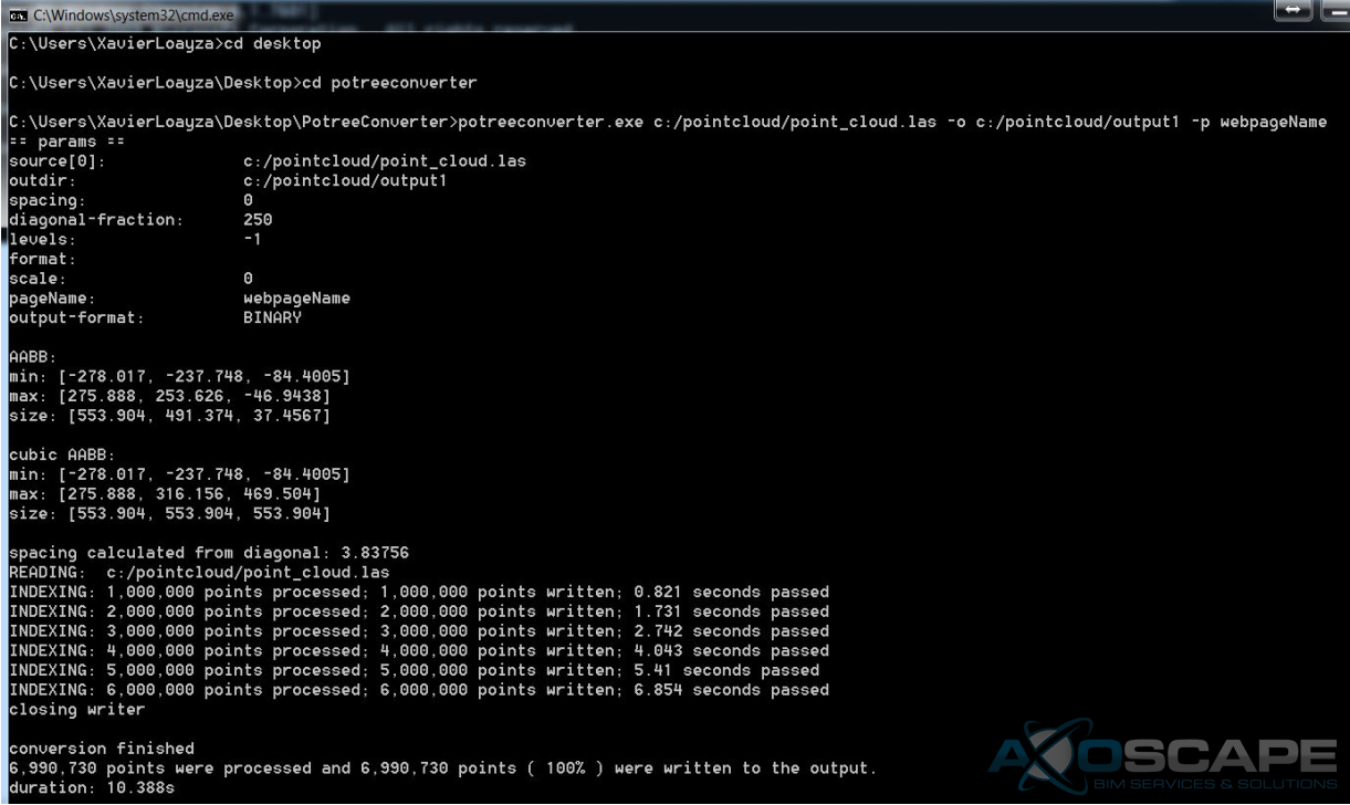
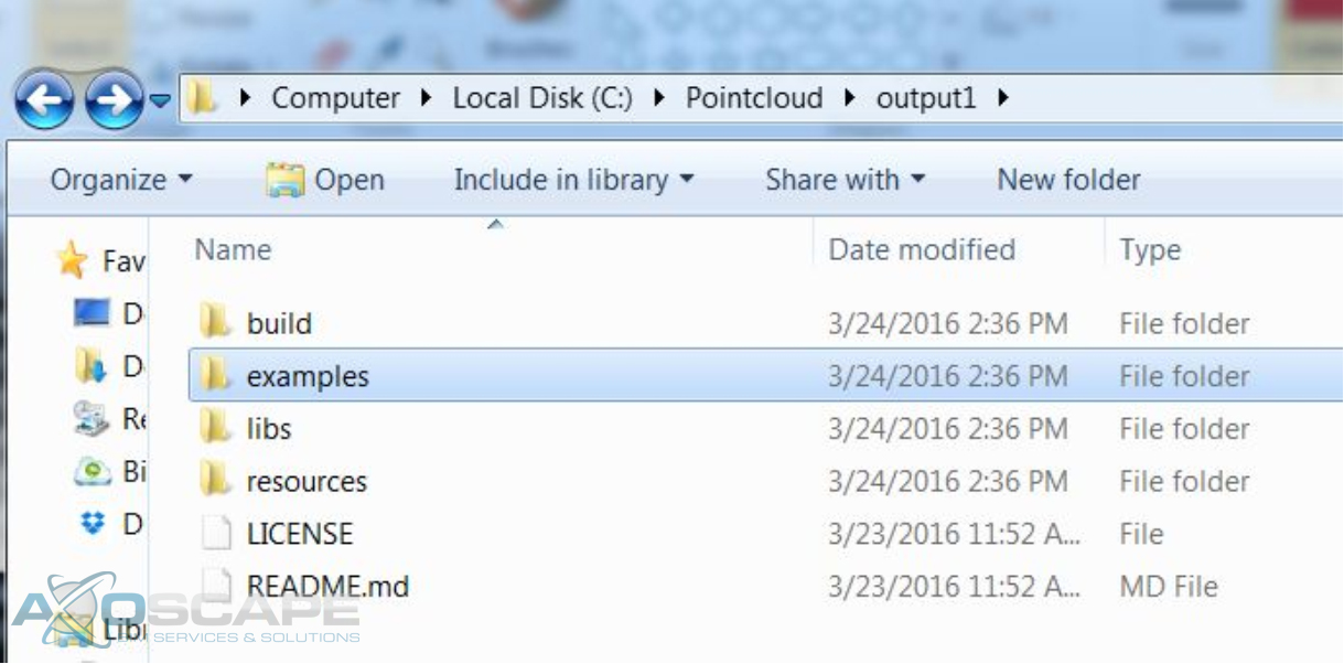
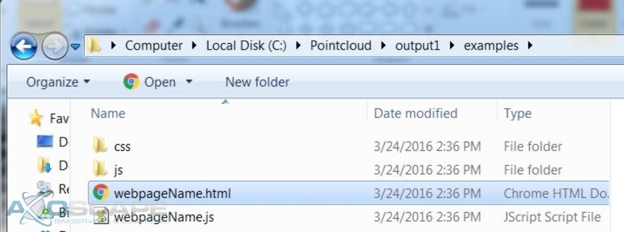
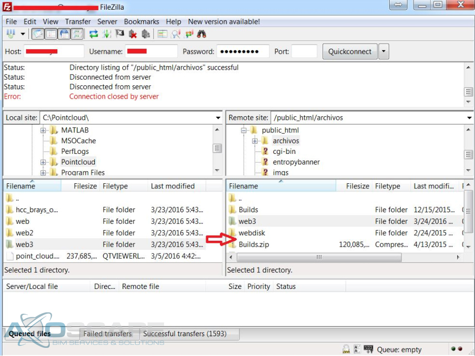
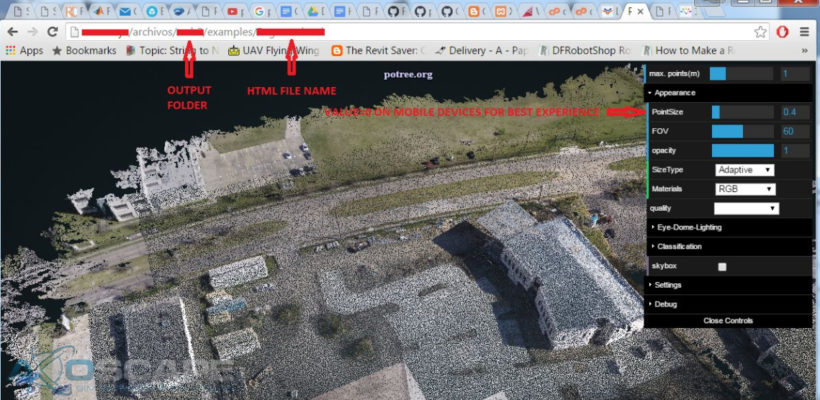
This short tutorial shows how to share 3D point clouds using potree.org, an open source web tool. Potree Converter converts .las, .laz, binary ply, xyz or ptx files to a format file readable for web browsers.
Steps:

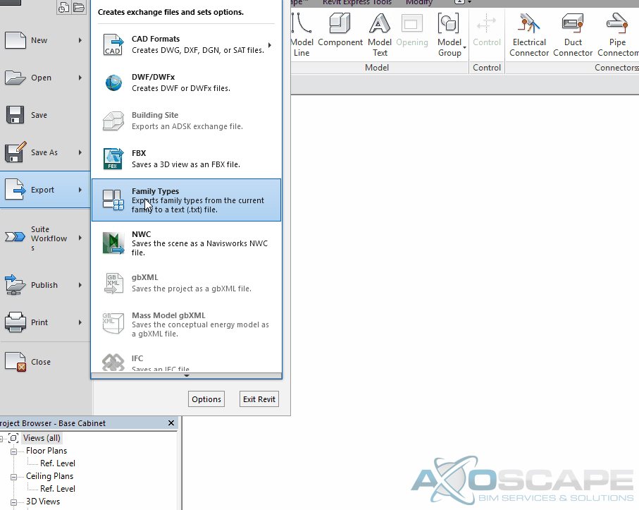
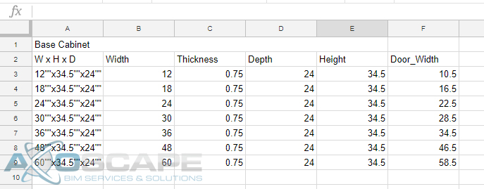
Why spend hours and minutes trying to create a million different types when it takes a few minutes to create a type catalog. Not that many users really apply this method, but it’s very useful and easy.
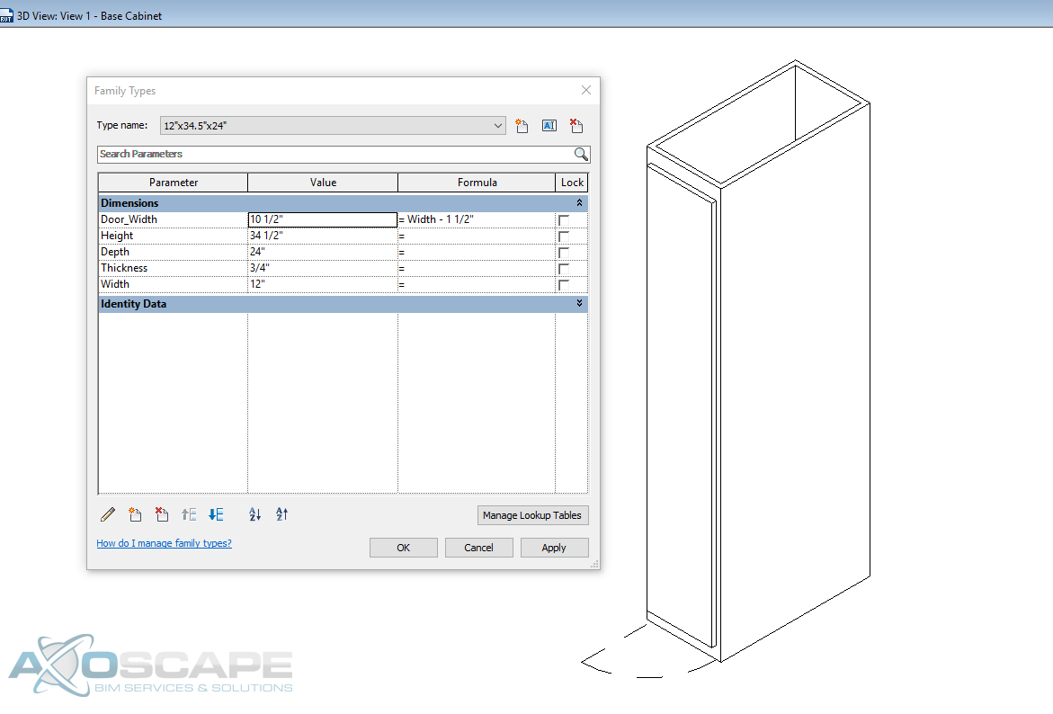
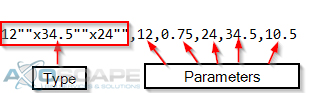
 The txt file will have one long strand of text and it can be a little confusing to understand at first. The file will contain all the parameter names, all the types that were created(before exported), and all the input to the parameters. Here is how it is broken down.
