Ignacio Rodriguez

Ignacio Rodriguez

Why is BIM Coordination Important?

BIM coordination: What is it really? Is it a matter of drawing blocks or cylinders and calling it a day? Let’s break it down. BIM stands for Building Information Modeling. When someone mentions BIM Coordination they’re referring to a 3D model that will help subcontractors make an educated guess on how to adjust their corresponding trade. Prior to BIM, subcontractors had to coordinate in the field. By doing pre-coordination it helped save time and headaches in the field.

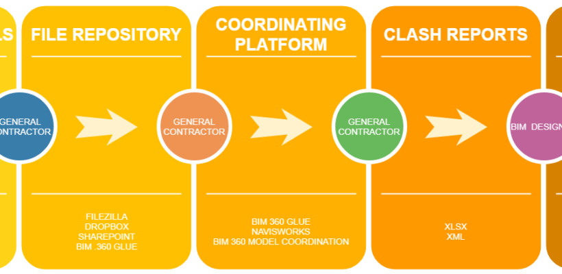
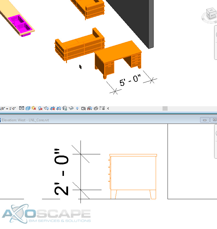
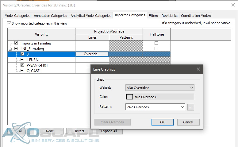
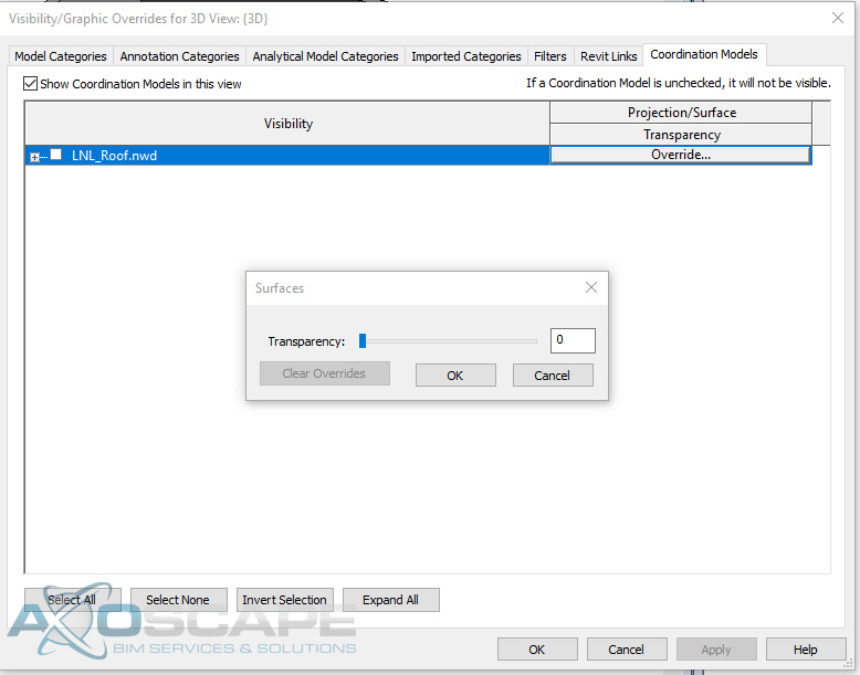
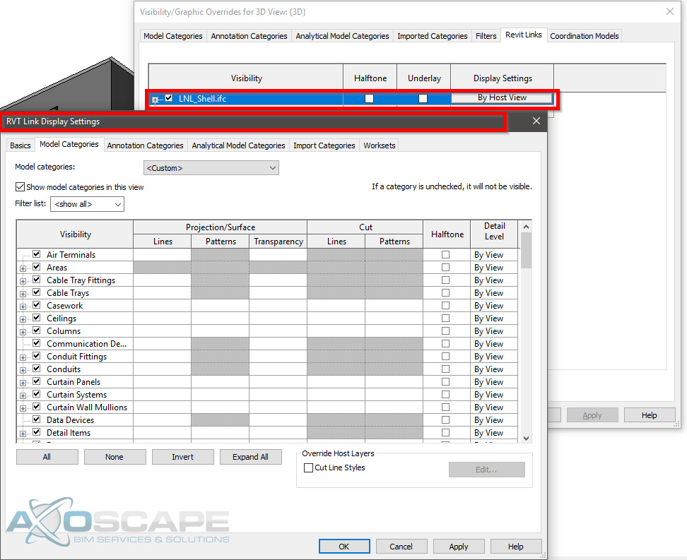
It would be nice if it was possible to crop certain parts of the building or change the transparency of a system in the field to be able to view things but technology isn’t there yet. In this article, we will break down each phase of Coordination. Starting from the creating stage, moving to export/uploading, coordination and clash reporting, and wrapping it up with RFIs.

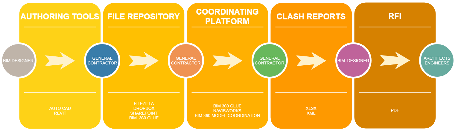
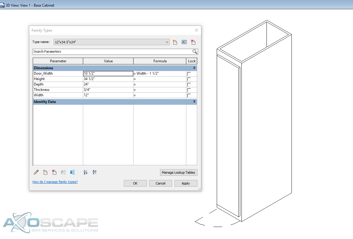
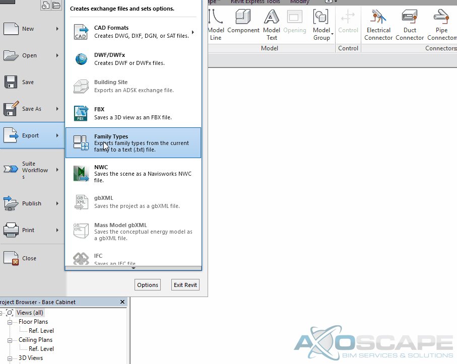
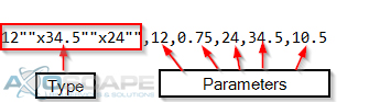
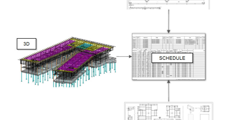
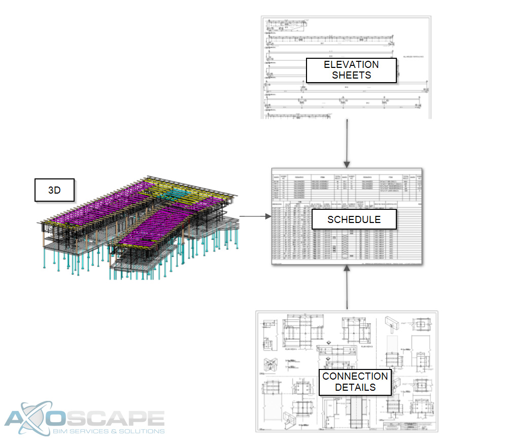
When a BIM coordination initially begins, all trades agree upon certain standards. For example, minimal pipe sizes, file naming conventions, upload scheduling, meeting scheduling, and project timeline. When detailers start modeling their starting point begins with the contract drawings and submittals. Once the detailers have most of their trade modeled they would export models and upload into an authoring tool (depending on the platform they’re working on).

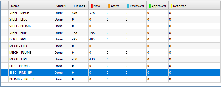
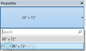
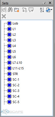
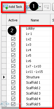
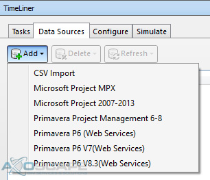
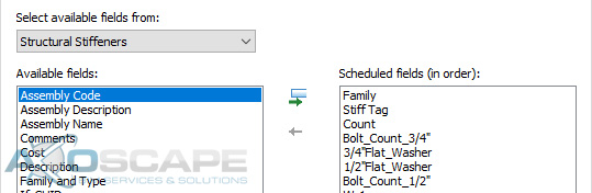
All trades upload their corresponding models with the file naming convention discussed during the kick-off meeting. Below is an example of what the General Contractor’s BIM Coordinator normally asks for when it comes to model naming. It will vary from GC to GC.

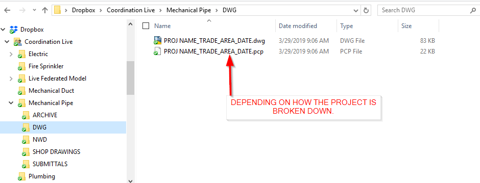
Another thing to look at from the screenshot is the folder structure.  As soon as the coordination team uploads their BIM models into the file repository the GC’S BIM coordinator combines the files.

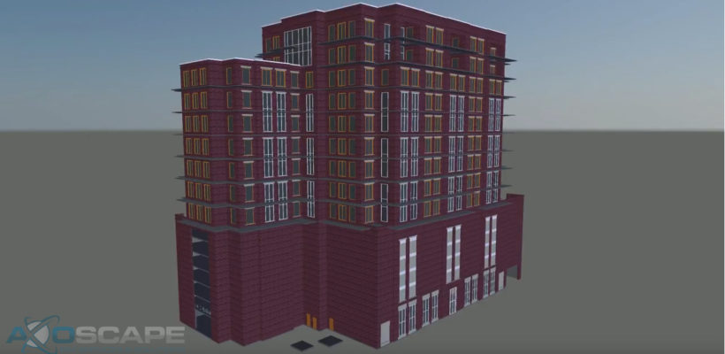
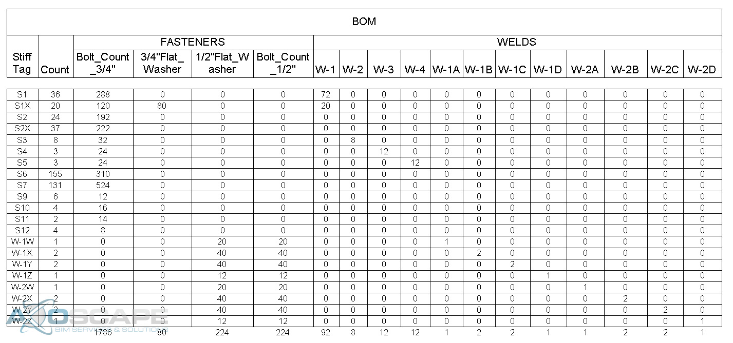
Once all the BIM data is implemented the coordinator saves the combined file as a federated model in Navisworks or BIM 360 Glue and start generating clash reports.

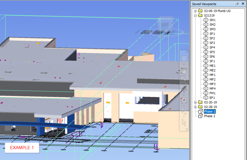
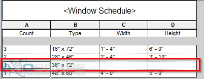
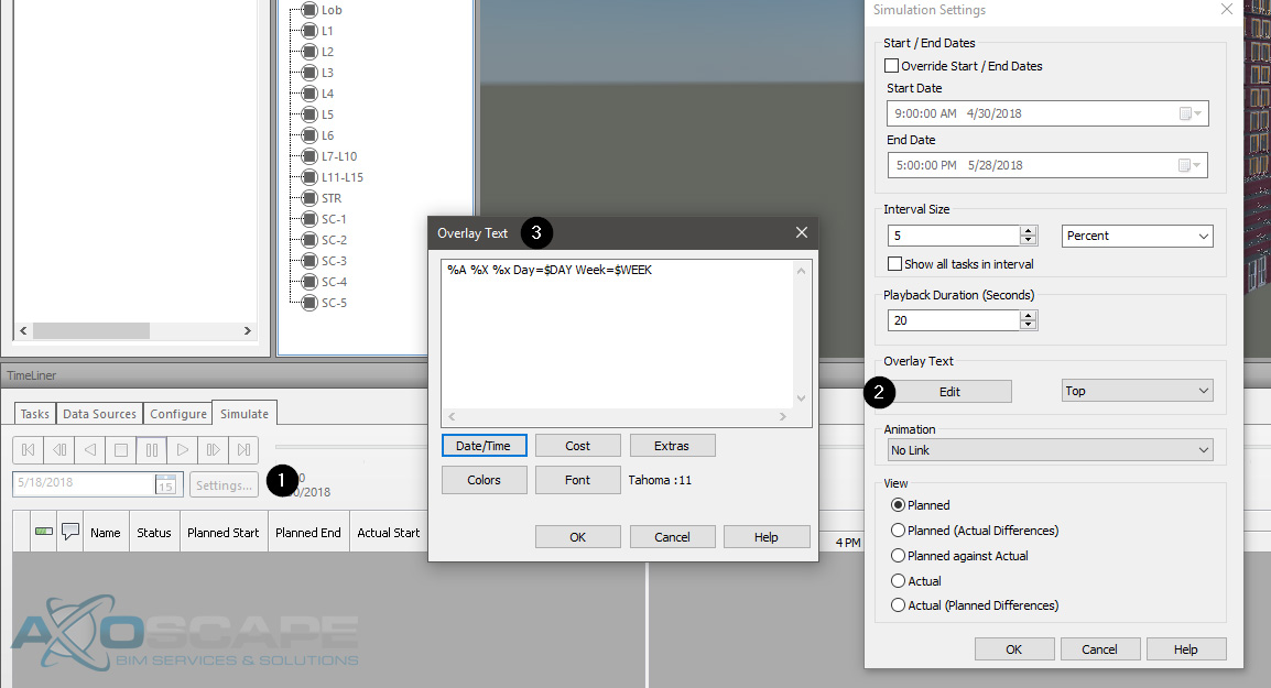
After running and reviewing the report the coordinator would then either save viewpoints from within Navisworks/BIM 360 Glue (Example 1).

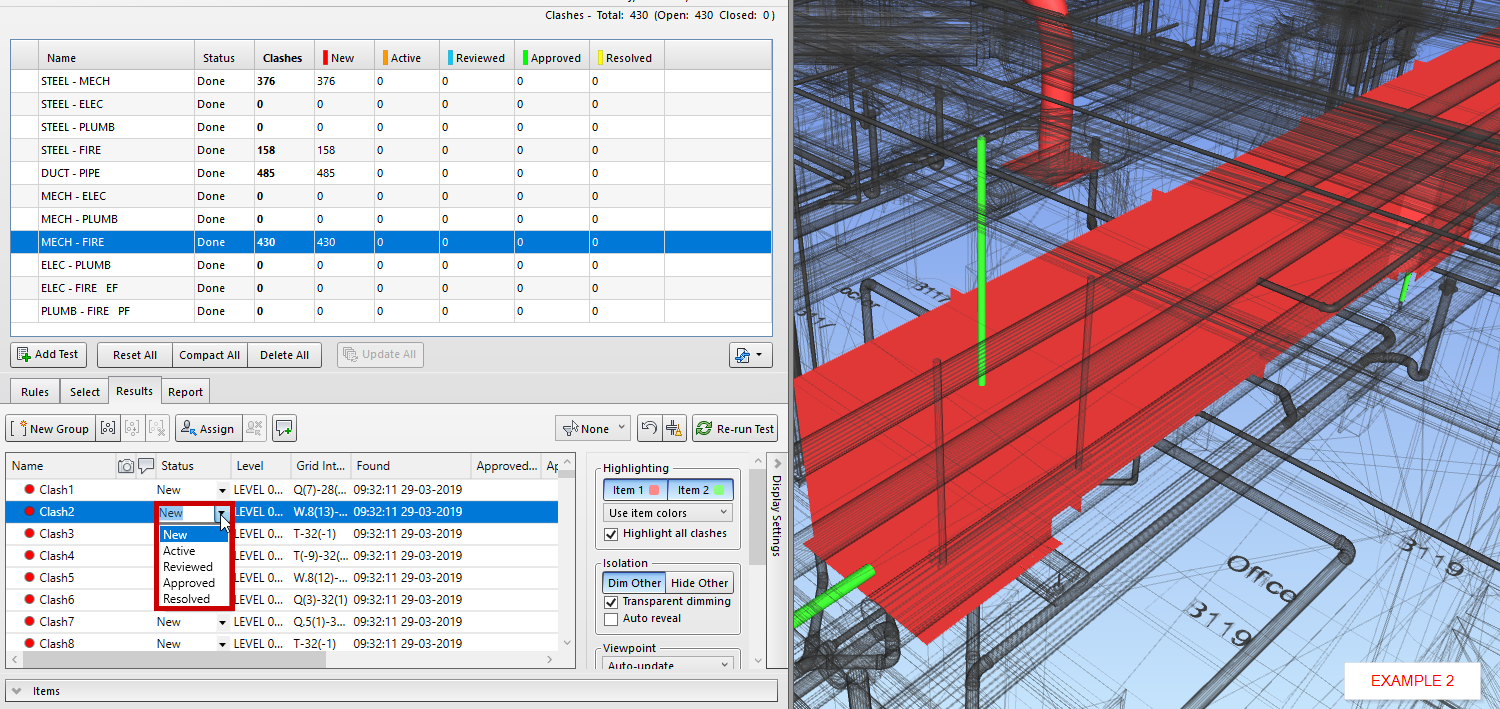
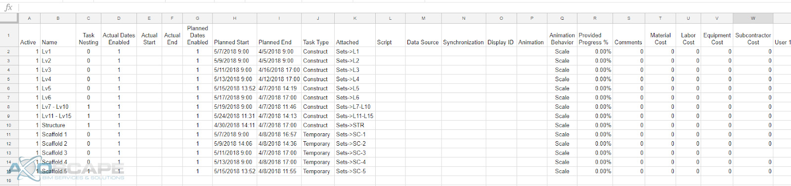
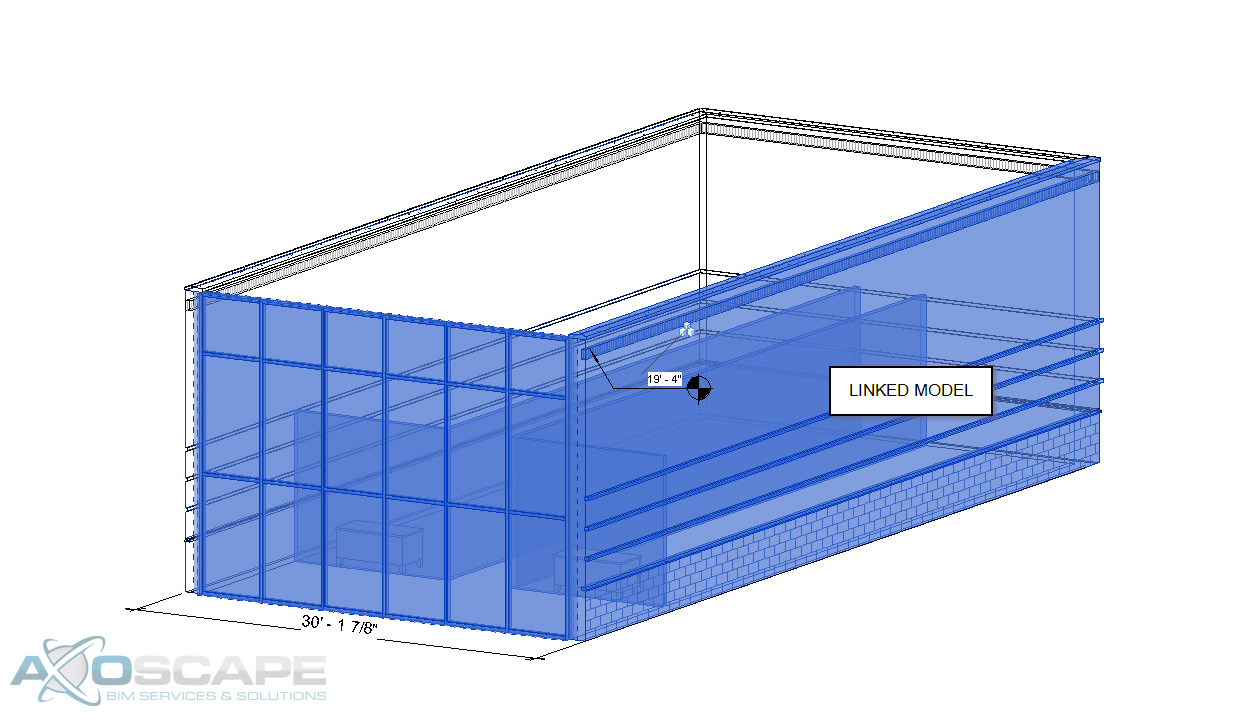
Or they will mark them on the report as “Resolved” “Reviewed” or “Approved” (Example 2).

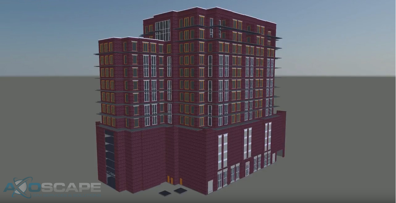
After the coordinator creates the clashing set the coordination team meets to discuss a plan of action. The team reviews all the clashes and eventually encounter an area where they will require a course of action from the Architect or Engineers. For documentation purposes, the Subcontractor will submit an RFI (Request For Information). See image below.

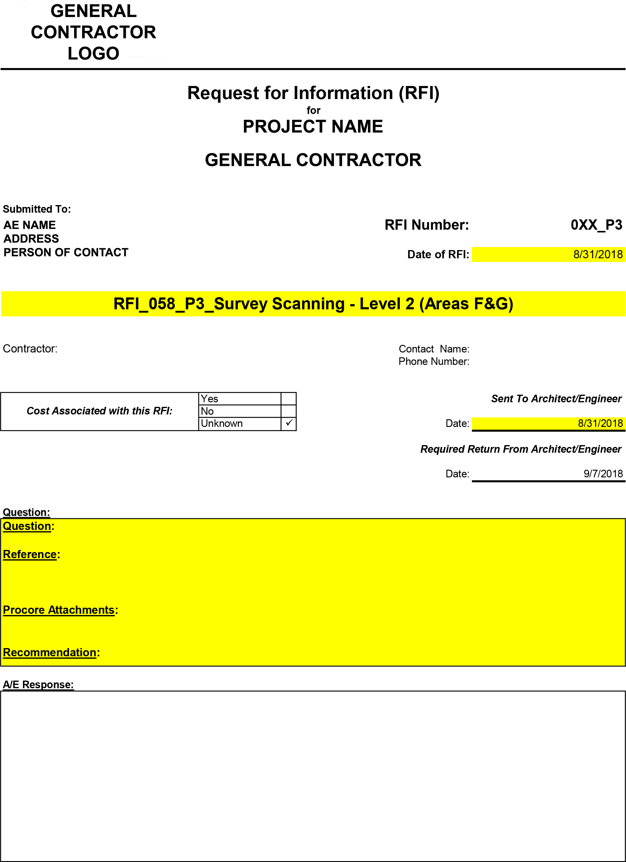
RFI’s are a crucial aspect of the whole coordination process because it may take the Architects and Engineers some time to come up with a solution or it could be a simple fix. The sooner the RFI is sent out the better, but also make sure to provide enough information (screenshots of a conflicting area, a room location, a very descriptive paragraph of the issue, and possibly some sections if needed). Once the RFI has been answered by the Architect or Engineer, the solution is sent out to the BIM coordination team to implement all changes and the cycle repeats until all clashes are resolved.

Let’s recap all the information we’ve gathered on BIM coordination and the process for it. First, a kick off meeting set standards and agreed upon, which will lead to the modeling process where detailers model their corresponding trades. The detailers will then upload their models into a file repository where the BIM coordinator download the models and assemble a federated model and generate a clash report. Once the BIM coordinator reviews the report the detailers meet to review clashes. If a clash cannot be resolved then an RFI must be sent out to the AE for review.  Afterward, a solution will be sent back that the detailers implement. This cycle continues until the project is fully coordinated and handed off to the Owner.

Read More

How Revit’s Origin Works

Everything in this world has an origin, a starting point, including Revit. The origin point is useful in many ways to us, especially when there’s collaboration involve with a handful of users with multiple models in one project. It allows the user the ability to line up the models in various ways to make the modeling and noting process to run smoothly. Having the origin helps to coordinate with others a bit smoother, but it’s crucial to know how the models were built in order to link in Revit correctly. It’s just as important to know how to export the models as well in order to share the files from one user to another.

  1. The difference between linking models based off of the origin point, and also linking them based off of shared coordinates.
  2. How to set up a file with shared coordinates.
  3. How to export each method.

There are two different ways to link in Revit models into projects. Through shared coordinates and also origin to origin. The difference between the two is based on how the origin point is set up. When linking in a model through origin to origin, this is telling the model to use the same origin point as the reference point to line up both models. But when the user links in a model based on shared coordinates, it takes the origin point of one model and uses it as its own.

Setting up shared coordinates is a fairly simple process to go through. It may seem a bit complex at the thought of it but it’s really simple.

The image above contains a linked Revit file placed in at origin to origin. This will be the starting point for the shared coordinates process. One thing that will have to be verified by the user is the elevation. Some models might be slightly off axis. All that needs to be done to correct this is open an elevation/section view and line up the levels if need be. Once this alignment is done, the next portion that will have to get aligned is in a plan view.

Once everything is lined up the way it needs to be, click on the Manage tab, select the drop-down arrow underneath “Coordinates”, and click on “Publish Coordinates”. By doing this, it’s telling the file this is your new reference point.

Once the coordinates are published to the model, the file will have to be saved in order for it to retain those coordinates. There are two ways to save the coordinates.

1. By saving the file where the model(s) are pulling the coordinates from. This will prompt a window informing the user that it’s about to save those coordinates onto the file.

Click save and continue saving the project. Here’s a rule of thumb when it comes to this portion of the saving process. The file with the updated coordinates will need to be closed out in order for the coordinates to be saved onto the file, or else it will send an error message explaining why it’s not able to save the coordinates.

2. Saving the file through Manage links. I would recommend this when there are multiple models involved. Select the file(s) and at the bottom left-hand corner there’s an option to “Save Positions”. Click on that and the same save window will be prompt as it did on the first option.

There’s a difference when exporting each model. Similar to how each model is linked into the project there’s a slight difference in how it’s exported as well. See below.

The most crucial part when it comes to exporting is selecting the coordinate system basis.

If the coordinate system basis is not set up correctly, then the model when linked into Navisworks, Revit, or AutoCAD will be floating out in the middle of nowhere.

I hope this was very informative, but just to recap on everything that we went over. The difference between origin point and shared coordinates. How to set up shared coordinate system. Last but not least how to export both methods out to a dwg format.

Read More

Linking It All Together

As a Revit user when starting off a project, the Project Coordinator will distribute some files to link into your model as a starting point. They will typically send out dwg, RVT, and/ or NWD files. There is always a project that will throw a curveball to the project. One of the biggest curveballs anyone can get hit with is working with a new file type. In this case, I will be discussing some differences from working with prototypical file types versus something like an IFC and a NWD.

In most cases, an RVT file would be the ideal format to work with since Revit understands it completely. Dimensions strings and elevation tags are a few of the annotation features a Revit user will be able to use on a linked RVT file.

Another great feature the user has when linking another Revit model is the align command. This is very crucial when lining things up with another model. Reason being is the fact that the user is able to select the component. Having this ability helps to review some of the parameters from this file.

The best part about linking another Revit file into a project is having the ability to schedule out everything from the project. Since it only contains Revit components the schedules will be 100% smart. Visibility graphics can override components within Revit, which means the linked RVT file will be affected as well. BUT it also has its own visibility settings in case the user doesn’t want to change a few components of the project.

DWG’s are the next typical file type to link onto a project. This file type limits the user on some of the things that can be achieved. For instance, the ability to use the elevation tag. However, by creating a dimension string, the user will still be able to find out the height of something.

Aligning items to faces of a DWG is a plus when it comes to lining things up nicely especially when it is at an angle. The only thing that can be overridden on a DWG is the line weight, color, and the line type.

If a schedule is created to read all the furniture equipment in a project, it will be blank since Revit does not recognize DWG elements.  However, there is the ability to insert blank rows and insert all the information for the DWG elements with the caveat of manual updates. 


NWD’s limits the user on what they can and can’t do. From working with NWD’s, the idea behind it was having the ability to coordinate within Revit. With an NWD model, the user is not able to select any of the elements or even change the color, line type, nor the line style. The only thing that can be overridden is the transparency level.

Now IFCs can be tricky to work with. Since IFC’s are typically produced from a sketchup model, all the elements are faces and not solids. Which means if the person that created the IFC model accidentally shifts a vertice on a face the whole face might not display correctly in Revit. This will cause problems when trying to align elements.

One good thing about IFC models is having the ability to override components similar to how the user would if they were working with another Revit model.

It is able to recognize all the different components. With IFC’s the user is able to copy and paste elements, BUT I wouldn’t recommend it since it will only load the copied elements from the IFC model. Here is an example of copying a window from an IFC model vs the window library in a project.

IFC Library

Revit Library

Another thing about copying the elements from an IFC model into the Revit file is if a schedule was created to read all the windows, the copied IFC windows will come out blank due to no size parameters.

If the IFC file is on Revit 2018, it will allow you to input the size in the window but it’s not 100% accurate due to the window not being a RFA (Revit family). Which means any size can be placed on the window but it will not reflect the physical model inside the file.

In conclusion, using a Revit file or an IFC model can be some of the best references. Since the IFC files act similar to how a Revit file is with the exception of a few parameters. DWG is the next best thing to work with, and if there’s any coordination involve with any MEP components. Or if the project is fairly large then I would use a NWD model to minimize the file size. Especially if it’s only to reference on the location of elements.  

Read More

Navisworks Works

Typically when people hear the word Navisworks they automatically think of clash detection… Is that all that Navisworks is really capable of? The answer is No.

There are a variety of things possible through Navisworks. For instance, creating a simulation. It is one of the most beneficial ways to get organized out in the field, and cut down on dead time.

Simulation

This process consists of a schedule with start dates, end dates, and phasing. With the simulation capabilities, it is possible to simulate the order and process of how things will occur out on site. Here’s a glimpse of what the schedule looks like.

There are multiple ways to schedule things out. The first way would be within the program itself. To start scheduling components, they will have to be apart of a set.

(A set in Navisworks is a group of selected components.)

Once all the sets are formed, then the task will need to be created and named accordingly. The name of the task will appear on the simulation as the video progresses.

There are settings to control the content that is visible on the side of the screen.

Within here, the dates/ times can be adjusted to display actual dates/ time (May 2, 2018, May 3, 2018, etc) if needed, or it could be a generic date etc (day 1, day 2, day 3…) There are plenty of other factors that can be included.

Once the task is created, the next step will be to attach the sets to the corresponding task. To attach sets to a specific task, right click on the “attached” column and go to the “set” that needs to occur at that task.

Lastly, set all the attachments to a “task”, and then add a start and end date to each one.

An alternative way to set up a schedule is to import a “csv” file (comma-separated values). This process involves more typing, BUT it’s a lot faster in the long run. The sets will have to be configured beforehand in order for this to work. Only critical step in this process is to have the nomenclature under the “Attached” column match the “sets” nomenclature, or else the “Attached” column will be empty.

The chart above represents the layout of how it’s supposed to be laid out before importing into the Navisworks file. To import the csv or any other excel file format, go to “Data Sources” > click “Add” > select the file format that will be imported.

Once imported, it should populate the schedule within Navisworks. The only downside to importing a csv or any excel format is that it only populates Monday-Friday. Saturday and Sunday will remain empty and when this is exported, there will be a long pause in between Friday and Monday. Now if this isn’t a problem then this method would be ideal but if not, then there’s a little manual work to be done.

To export the simulation, click on the “Simulate” tab and click on a box with two arrows pointing to the center.

This will bring up a window with some export options. This portion is more of a personal preference and how the simulation will be used.

Read More

How to Save Time Creating Type Catalogs in Revit

Why spend hours and minutes trying to create a million different types when it takes a few minutes to create a type catalog.  Not that many users really apply this method, but it’s very useful and easy.

  1. Select a family with all the parameters that vary.
  2. Export family.

  3. Edit txt file that is generated.
    The txt file will have one long strand of text and it can be a little confusing to understand at first. The file will contain all the parameter names, all the types that were created(before exported), and all the input to the parameters. Here is how it is broken down.
  4. The beginning of the strand indicates the parameters that are built in the family. After each parameter, there will be a “,” to divide them.

  5. After all the parameter names, the “Type name” will start off the next portion of the strand followed up by the parameter input(same order as the parameters are listed above).

  6. The most efficient way to write all the different charts is a spreadsheet. It’s easier to read and understand what value corresponds to which parameter.

  7. Once all the values are plugged into the chart. Select all the Type and parameter cells and copy/paste back to the txt file like so. Delete the space and replace with commas.
Read More

Scheduling Beam Connections Using Shared Parameters

This workflow was created from a project for RM Rodgers, Inc., a subcontractor who specializes in wood beam systems with over 50 years of experience. This was one of the first projects where 3D modeling was required for coordination purposes. This article will cover how to schedule out beam connection components. Here’s a look at the schedule.


This schedule needs to reflect the everchanging conditions of the project and update dynamically. For example, if an existing connection is altered, the bolt counts and other parts change. In addition to the connection changes, the elevation sheets and B.O.M schedule must be updated.

This is your typical workflow when it comes to producing cut sheets for any manufacturer.


Manually updating every sheet in the project is tedious and time-consuming.  To avoid this manual rework, a shared parameter will provide automation. 

  1. Create family parameters for each connection in the Other category (Structural Stiffener category).
  2. Create shared parameters required for each family.
  3. Generate structural stiffener schedules for the connections.

Once you have all this information preloaded in the connection families, updates to scheduling are automated. Making it simple for the user to keep accurate counts on every component dynamically.

Read More