Ryan Nguyen

Ryan Nguyen

How to Create Custom Railing Profile

Railings are probably one of the harder tools to master in Revit. The menus and multiple sub-types of elements can be confusing. Don’t worry, we can handle this one rail at a time. Let’s start!

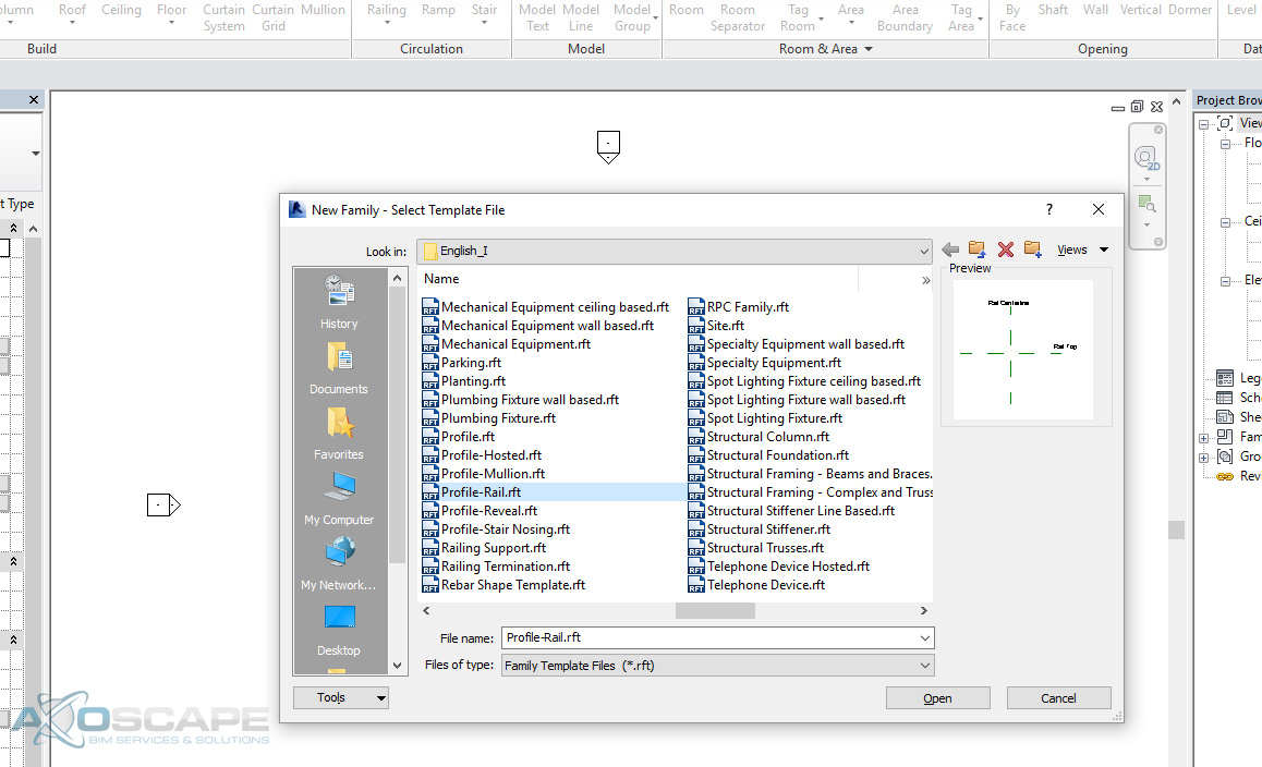
  1. To create a new railing family using the profile Revit Family Profile, go to “File/New/Family” and scroll to Profile-Rail.rft and Open.

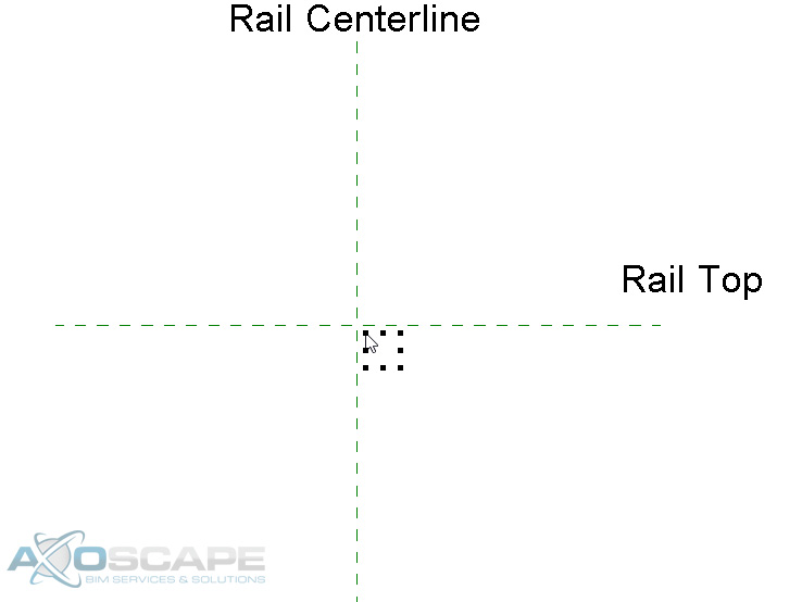
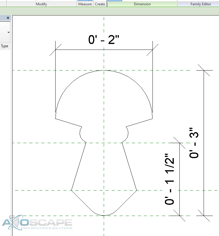
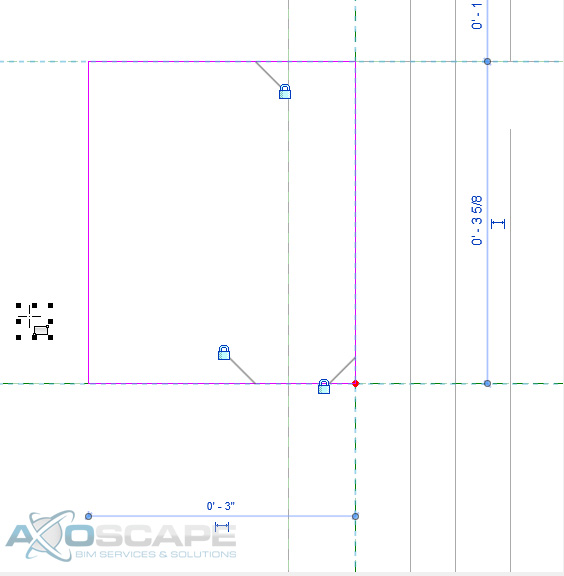
  2. Inside Profile-Rail, you get a Rail Centerline and a Rail Top. You have 2 ref. plans and both are defined origin as marked under properties. Which means the insertion point is at the cross-hair of the two ref. plans.

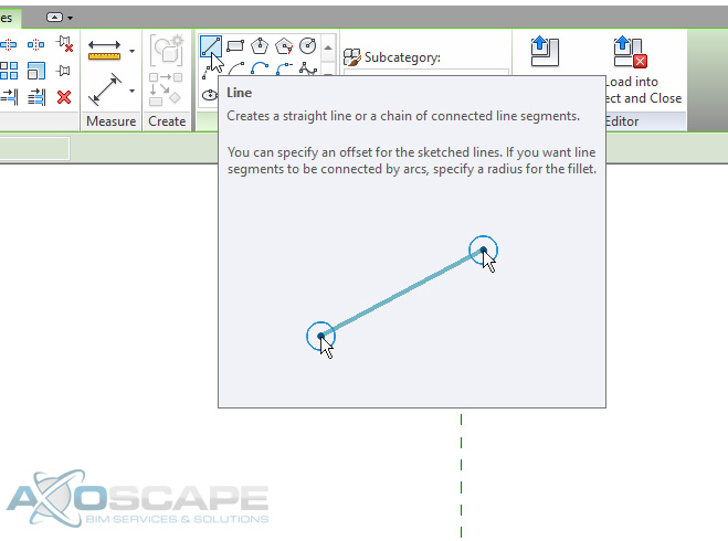
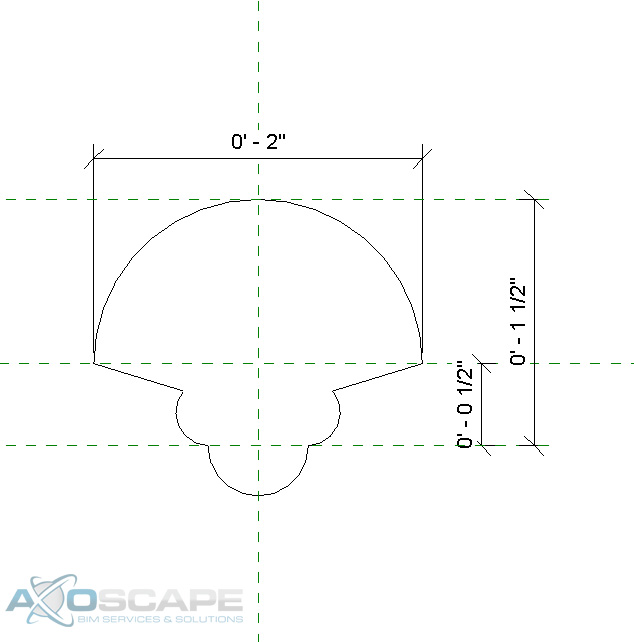
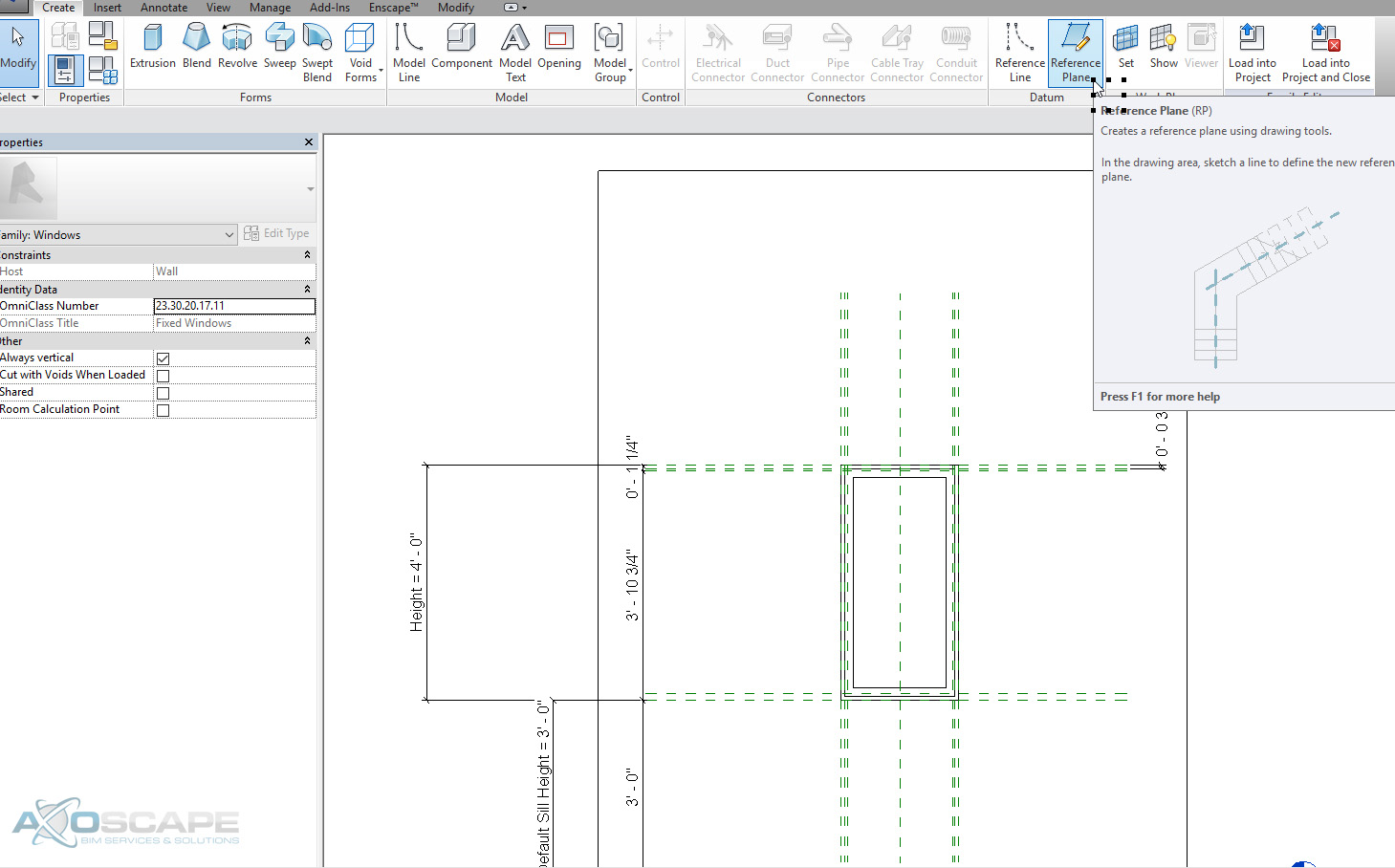
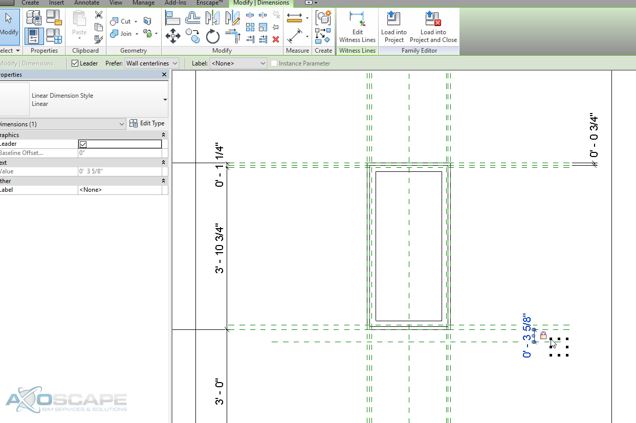
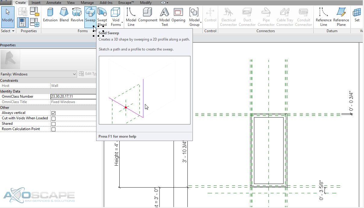
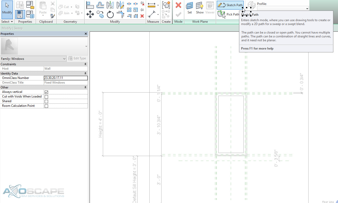
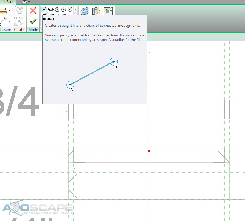
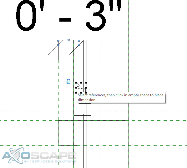
  3. Click the Create tab of the ribbon, line command under detail panel. Draw something simple to represent the rail of choice. Save the rail file family as Custom Profile 1.
    You can change the lower horizontal railing to any shape/size/height you would like to fit the railing profile in your project.


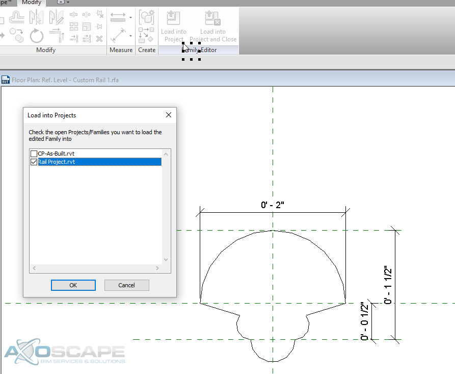
  4. Open the project with the rail you want to alter and load the rail profile into the project.

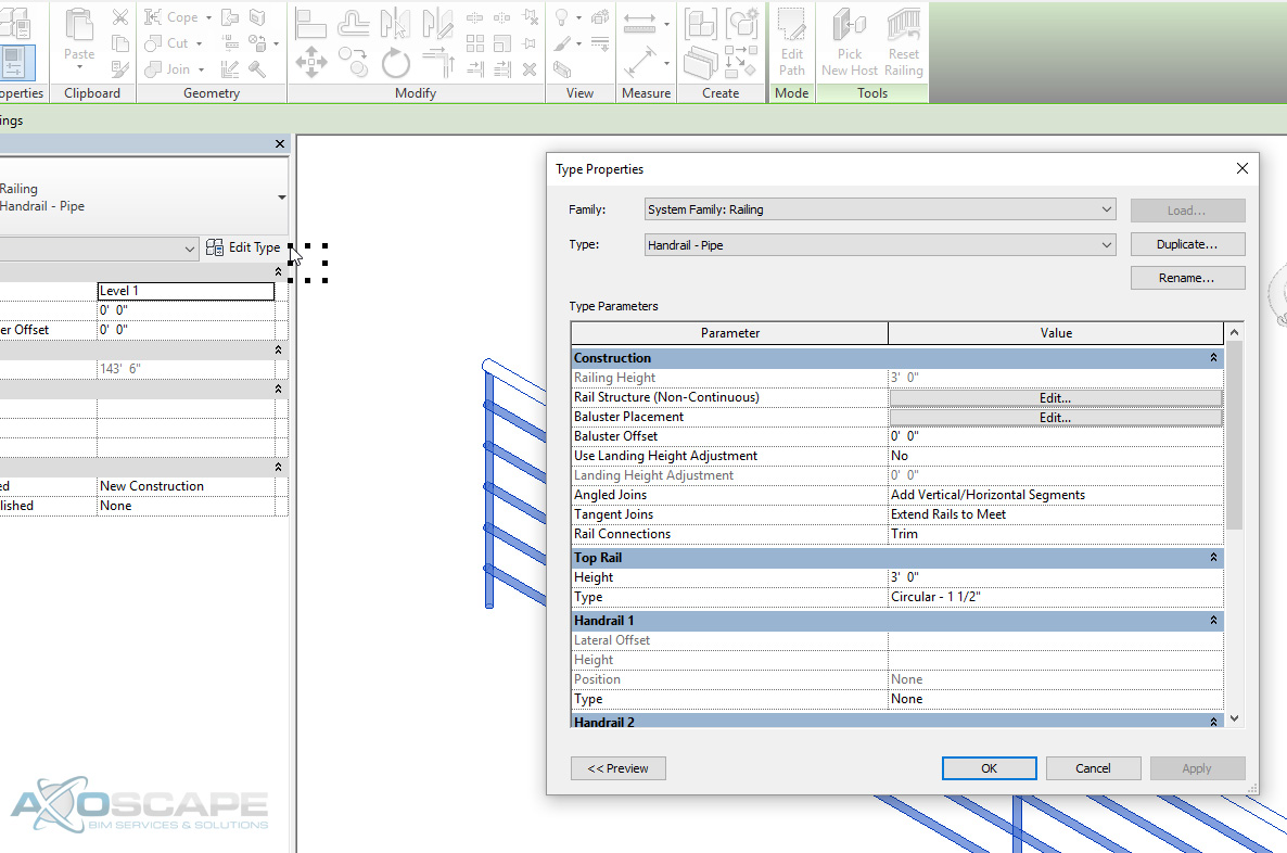
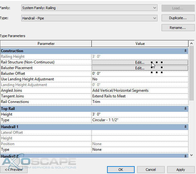
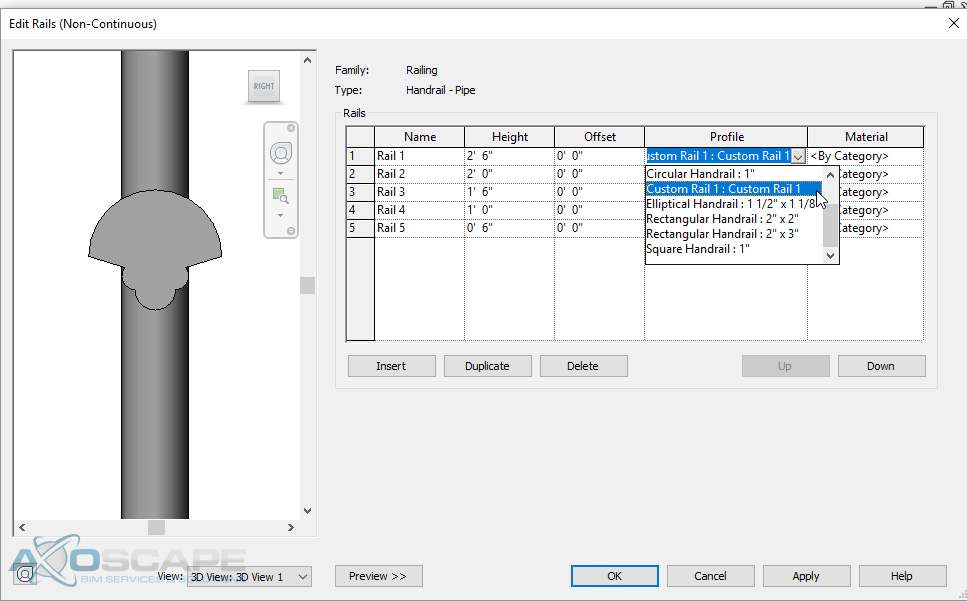
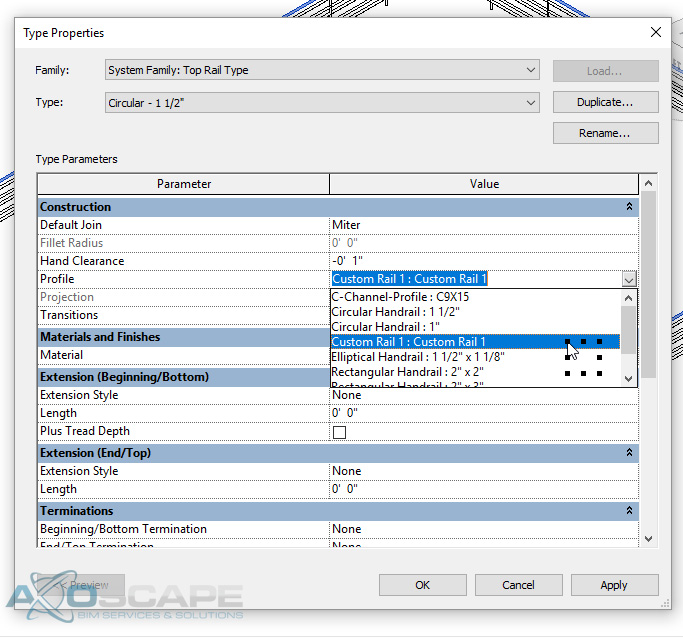
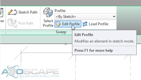
  5. Select the rail and go to the Edit Type. Once the Edit Type window opens, click Edit at Rail Structure (Non-Continuous) to open Edit Rails (Non-Continuous) window. Click the rail you want to change under Profile and you will see the Custom Profile 1 rail is there.


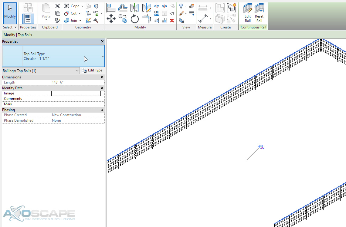
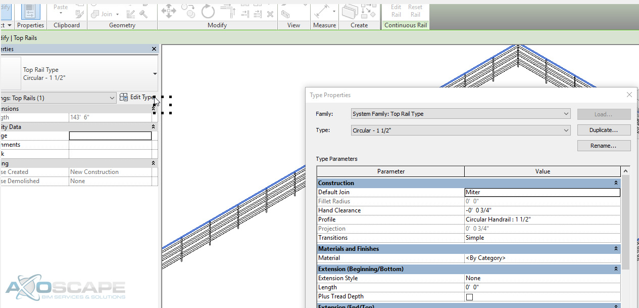
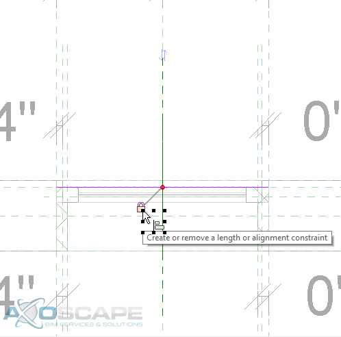
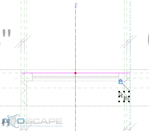
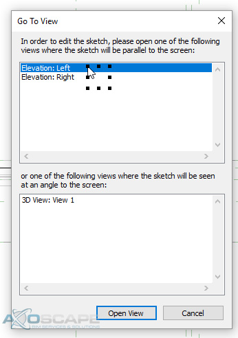
  6. As for the top horizontal railing, you can tab into the top rail. Left click it to select it. You will notice there is a pin feature located on the rail. The reason is that the railing system family has it as a separate object that you have to treat and adjust independently. So, unpin the rail to have access the properties palette under the type selector. Continue by following similar to step 5. Click Profile to access the profile for the top horizontal railing.


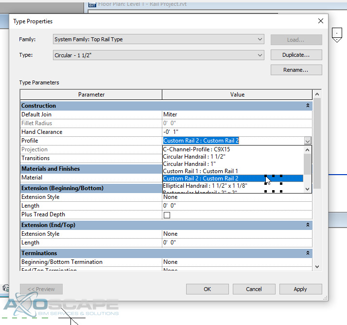
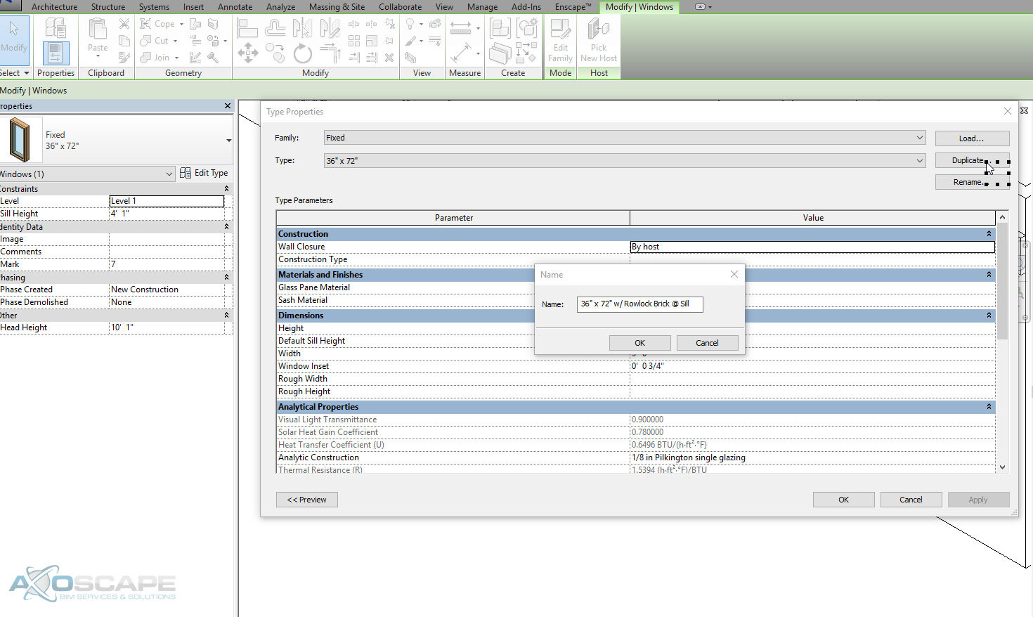
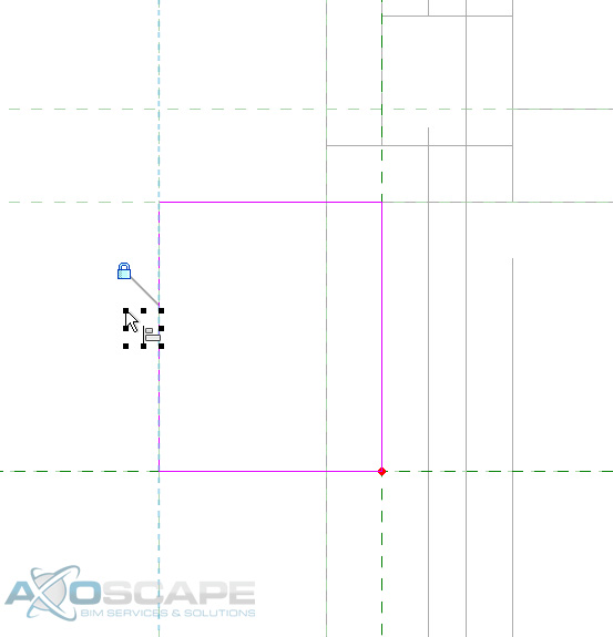
  7. This time, let’s create a Custom Rail 2 family to make it look a little different and load into the project. Click Profile and change the existing railing to Custom Rail 2.

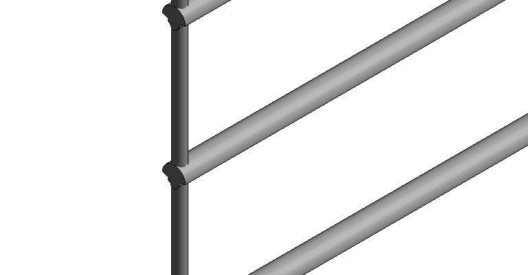
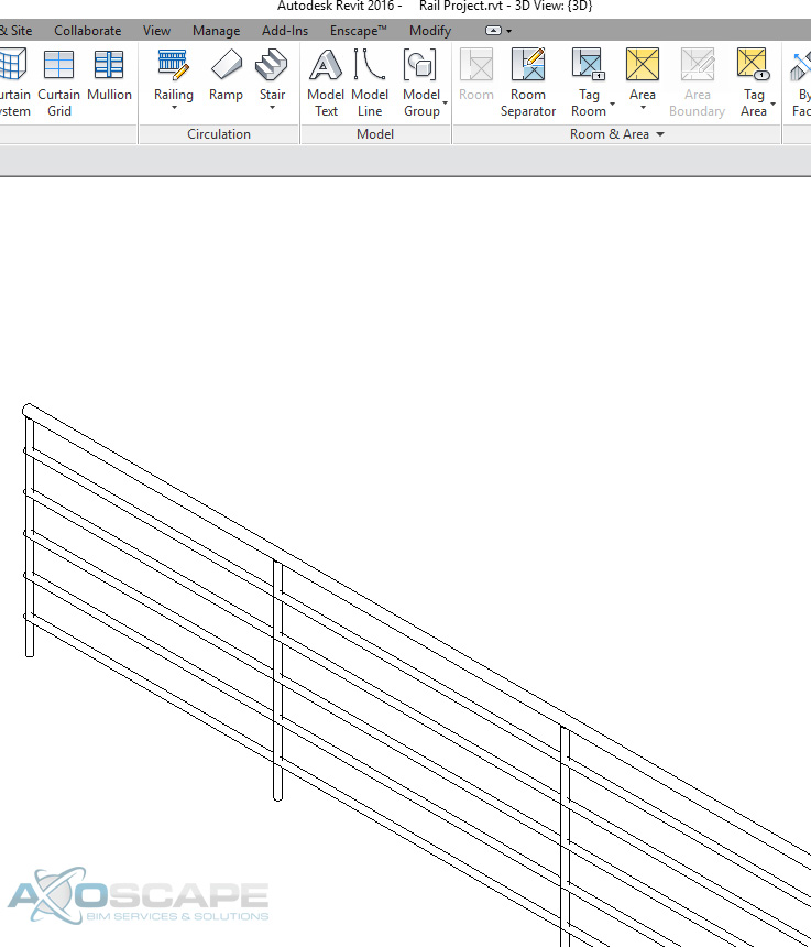
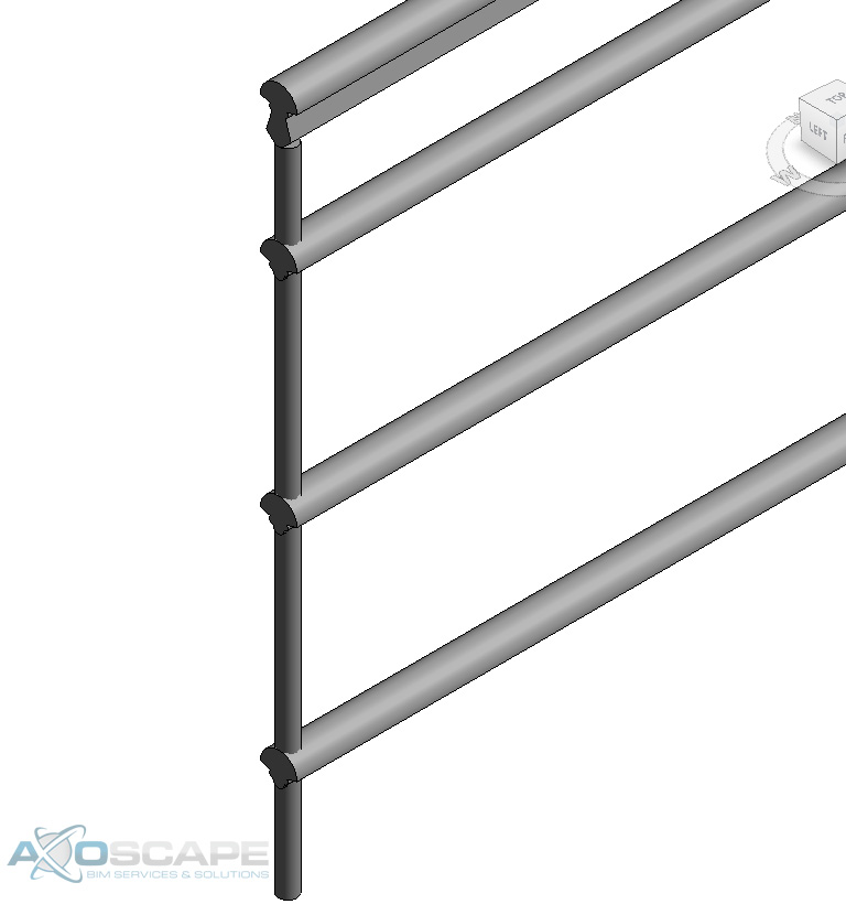
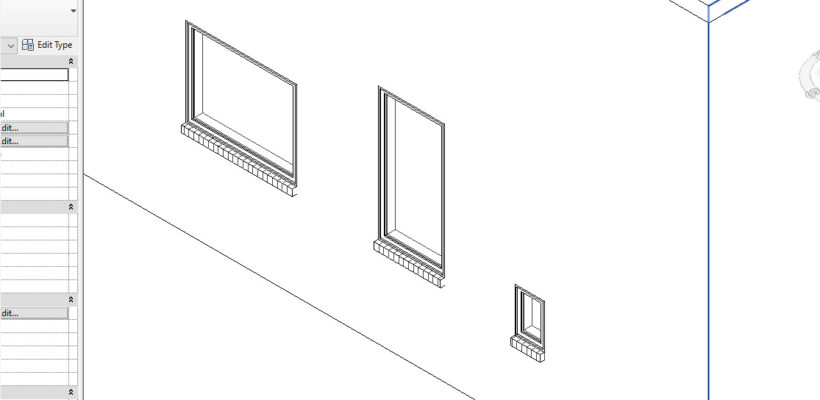
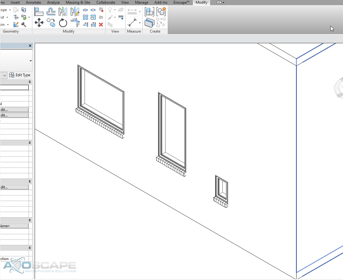
  8. The end result will be what is shown below. You can adjust as you please to make it the way you want it. Play around and just have fun with the design.

    Download the printable version here:

Read More

How to Add Rowlock Brick Sill to Window Family

When creating rowlocks bricks underneath windows, it is tempting to simply draw in sweeps and call it a day.  The problem with this technique is, if window moved or changes shape, those sweeps will not update which will require manual intervention. Instead, the better way of creating rowlock bricks at the window sill is within the window family. By building the rowlocks in with the windows, the rowlock will update automatically. 

  1. Select the window in the project to begin.

  1. Click edit family to edit the window family. Go to Elevations Exterior view and draw a new reference plane 3-5/8” away from the sill for the depth of the brick. Lock the Reference Plane.

  1. In the create tab select Sweep and sketch the path of the rowlock.

  1. But before drawing the path the work plane will need to be picked to draw off of. In this case, pick the new reference plane that was created.    

  2. Sketch a line and lock the line to the reference planes that encompass the window frame. Click Finish Edit Mode once done.

  3. Click “Edit Profile” under “Profile” to draw the profile of the rowlock brick. Go to the “Left Elevation” view to sketch the profile.

  4. Draw the brick sill to the preferred dimension and lock the profile to the reference plane. Draw another reference plane and lock the new reference plane to the inside face of window’s reference plane. Go back to the sweep and lock the last face to the reference plan.


  5. To test if the rowlock works correctly, go into a 3D View and it should show the brick sill. The brick sill should stretch with the width of the window.

  6. Change the material of the rowlock by clicking Material to open the Material Browser. Create a new material and call it Brick Soldier Course. In the “Surface Pattern” area in the graphics tab, click on “surface pattern”. Click Model and New to bring up the Add Surface Pattern. Rename the pattern, change the line angle to 90 degrees, change line spacing 1 to 2- 85/128” and hit OK to get out of the Material Browser.

  7. The final result after reloading the window family into the project. 

Congratulations! Now the brick rowlocks update dynamically. This method requires a bit of work to setup, but will undoubtedly save much more time down the road.

Read More