7 Key Features in Revit 2026
What’s New & How to Leverage Them with Building Information Modeling (BIM)

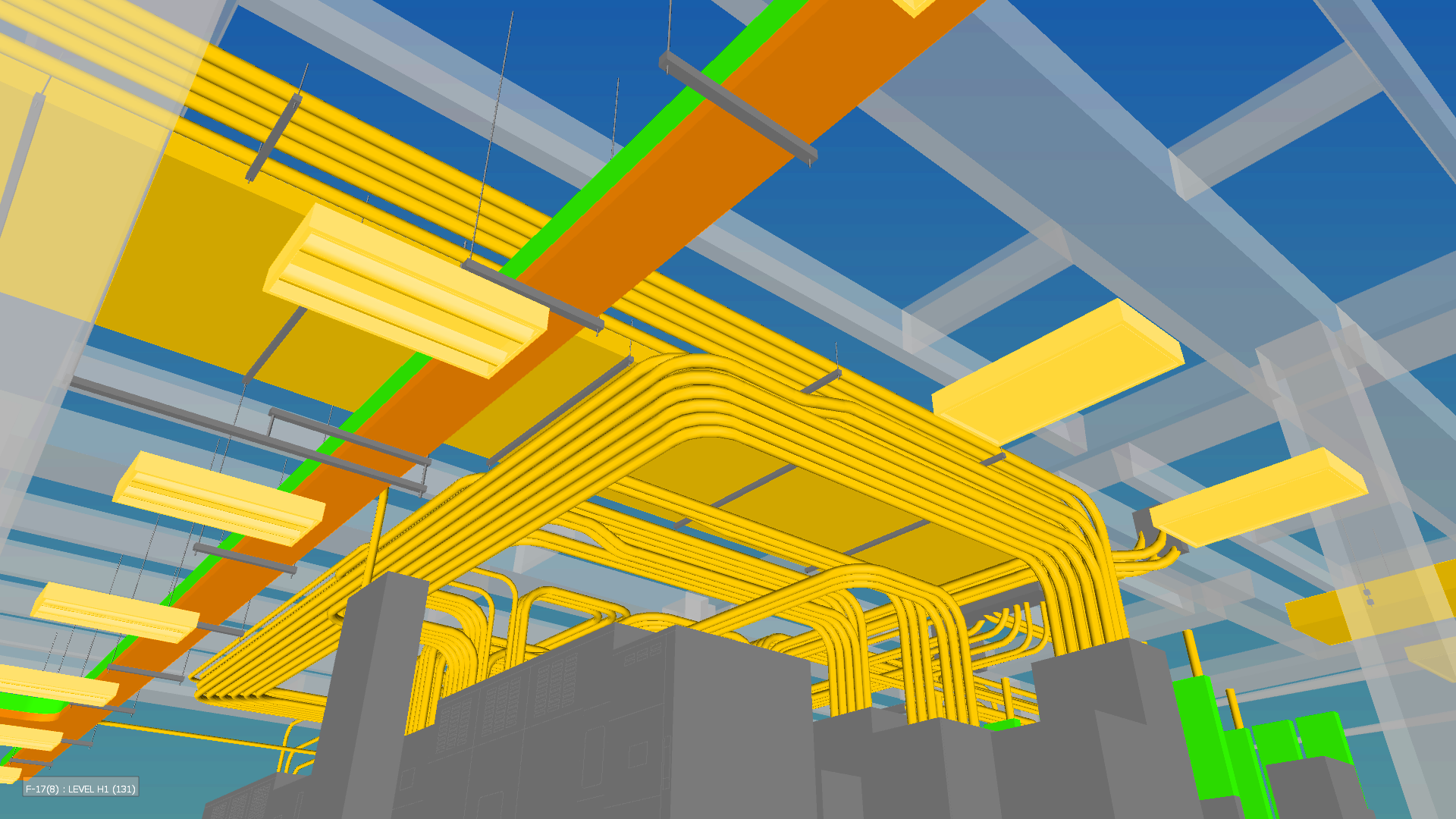
Autodesk Revit 2026: A major leap forward in BIM tools and performance.
1. Accelerated Graphics Tech Preview
Experience smoother navigation in both 2D and 3D views with the new Accelerated Graphics Tech Preview. Leveraging advanced graphics technologies like USD (Universal Scene Description) and Hydra, this feature enhances visual performance, allowing for more responsive model interaction, especially in large datasets.
2. ReCap Pro Mesh Plugin Integration
The integration of the ReCap Pro Mesh plugin enables users to incorporate large quantities of reality capture data directly into Revit without compromising performance. This is particularly beneficial for projects focusing on retrofitting and adaptive reuse, allowing for efficient modeling based on existing conditions.
3. Enhanced Documentation Tools
Revit 2026 introduces “View to Sheet Positioning and Automated Placement,” streamlining the documentation process by automating repetitive tasks. Additionally, shared parameters can now be used in family labels for Callout Heads, Elevation Marks, Section Marks, and View References, providing greater flexibility in documentation.
4. Toposolid Improvements
Site modeling sees significant enhancements with improved sub-division functionality, increased point thresholds (up to 50,000 points), and better collaboration workflows between Revit and Civil 3D. These updates allow for more accurate and flexible terrain modeling.
5. Structural Enhancements
Structural engineers benefit from the new Parametric Rebar Cranking feature, simplifying the modeling of cranked bars in congested areas. The introduction of point-to-point modeling for steel elements ensures precise placement without automatic setbacks, enhancing model accuracy.
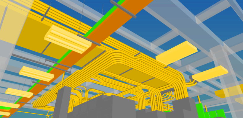
6. MEP Workflow Enhancements
Revit 2026 expands support for global electrical standards by replacing Wire Type and Wire Size with Cable Type and Cable Size, accommodating a broader range of conductor calculations. HVAC zoning is also improved, merging HVAC Zone and System Zone objects into more versatile System Zones, facilitating better equipment selection and distribution routing.
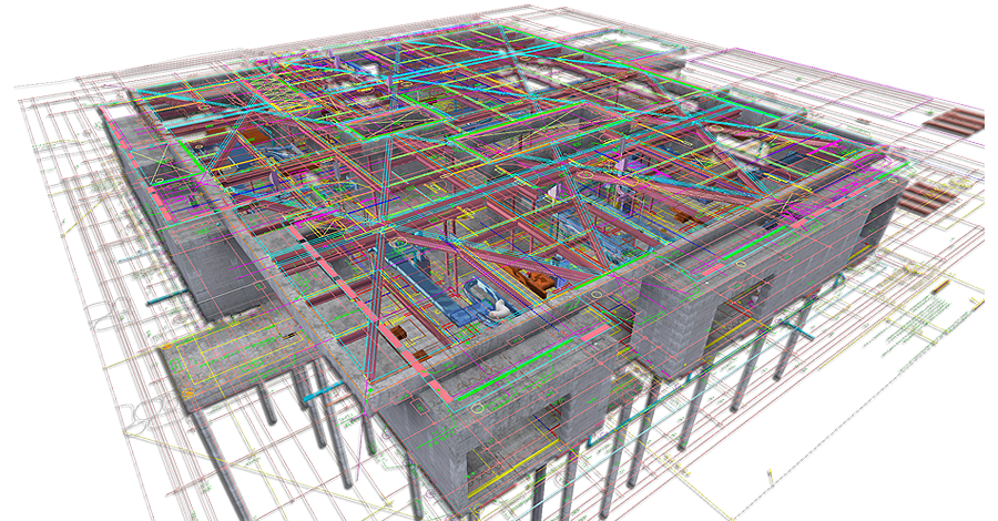
7. Improved Interoperability and Collaboration
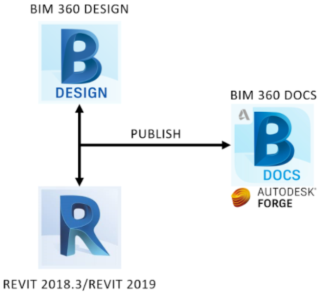
The new Manage Links Dialog now displays imported CAD files, providing better visibility and control over linked data. Enhancements to Coordination Models and IFC Link Orientation selection streamline cross-disciplinary workflows, reducing errors and improving collaboration.
📅 Join Us at BIM Meet Houston – May 27th
Excited about the new features in Revit 2026? Join us at our upcoming BIM Meet in Houston on May 27th! We’ll delve into the latest updates, share insights on integrating them into your workflows, and discuss how tools like Axoscape can enhance your BIM coordination efforts.
Whether you’re an architect, MEP designer, BIM manager, or simply passionate about building technology, this event is a great opportunity to connect and learn.
This post is based on Autodesk’s official release notes and blog updates. For a comprehensive overview, visit the Autodesk AEC Tech Drop blog.(Autodesk)
Stay tuned to the Axoscape blog for more updates and insights. Let’s continue to build better—together.

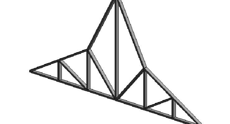
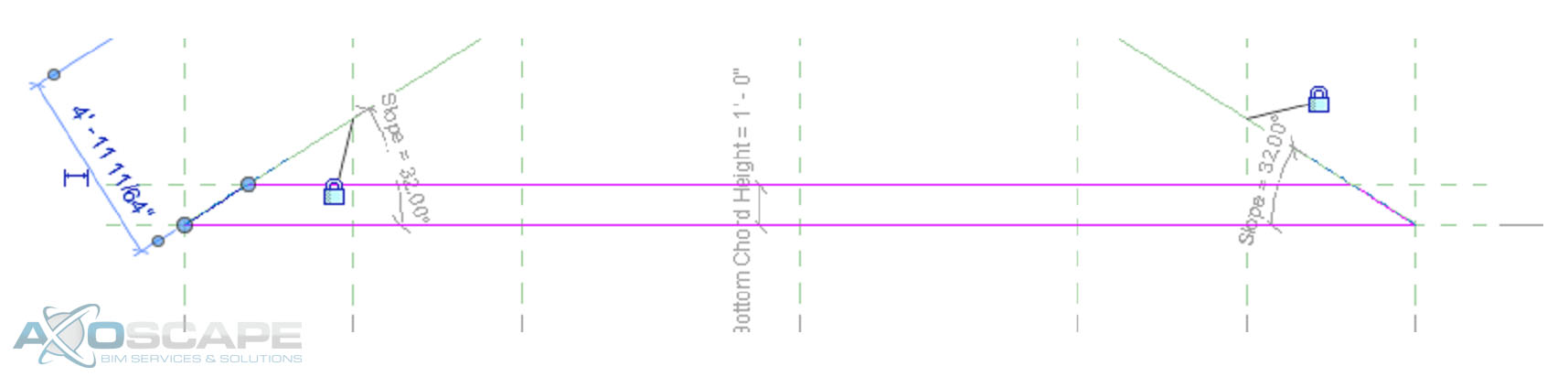
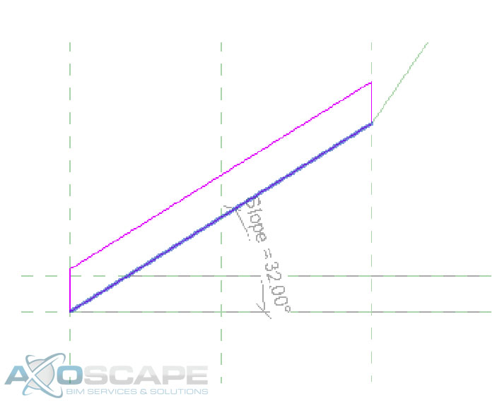
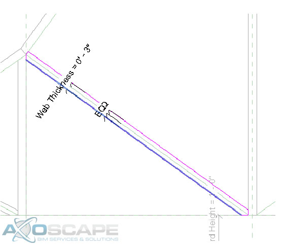
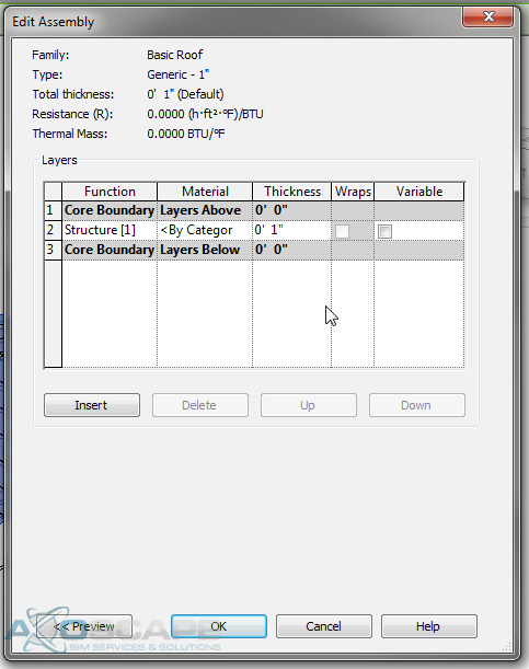
 ⦁ Extrude the webs on each side by using the two vertical reference planes on each side, also add a dimension parameter for the web thickness.
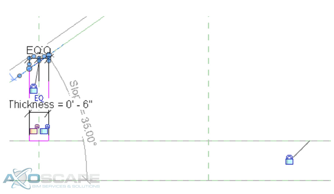
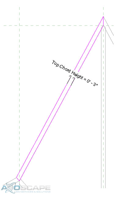
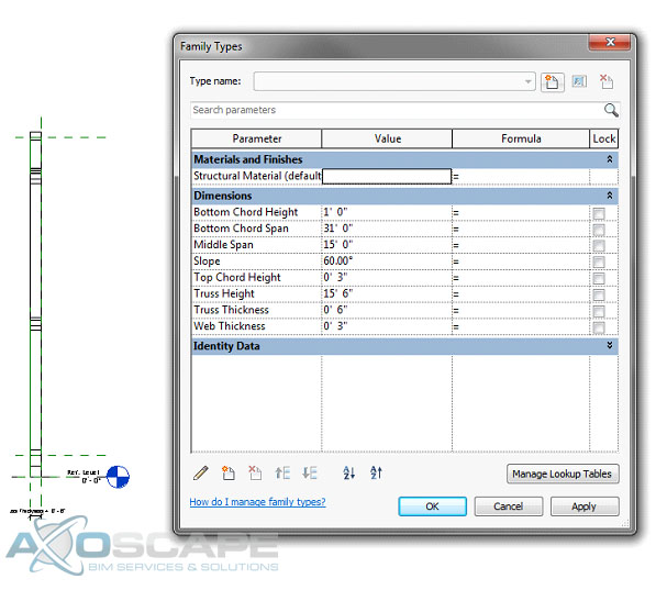
 ⦁ Use the extrude tool make middle web member the same way.
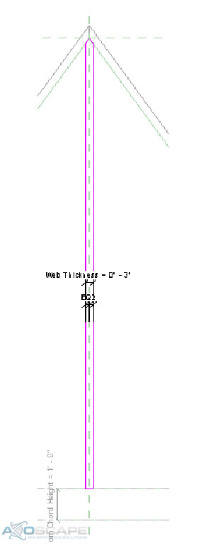 ⦁ Test to make sure things are working correctly.
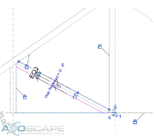
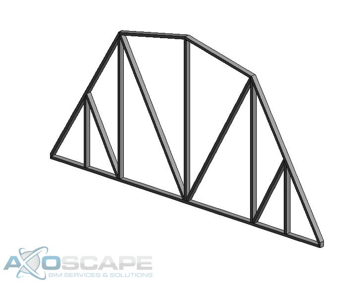
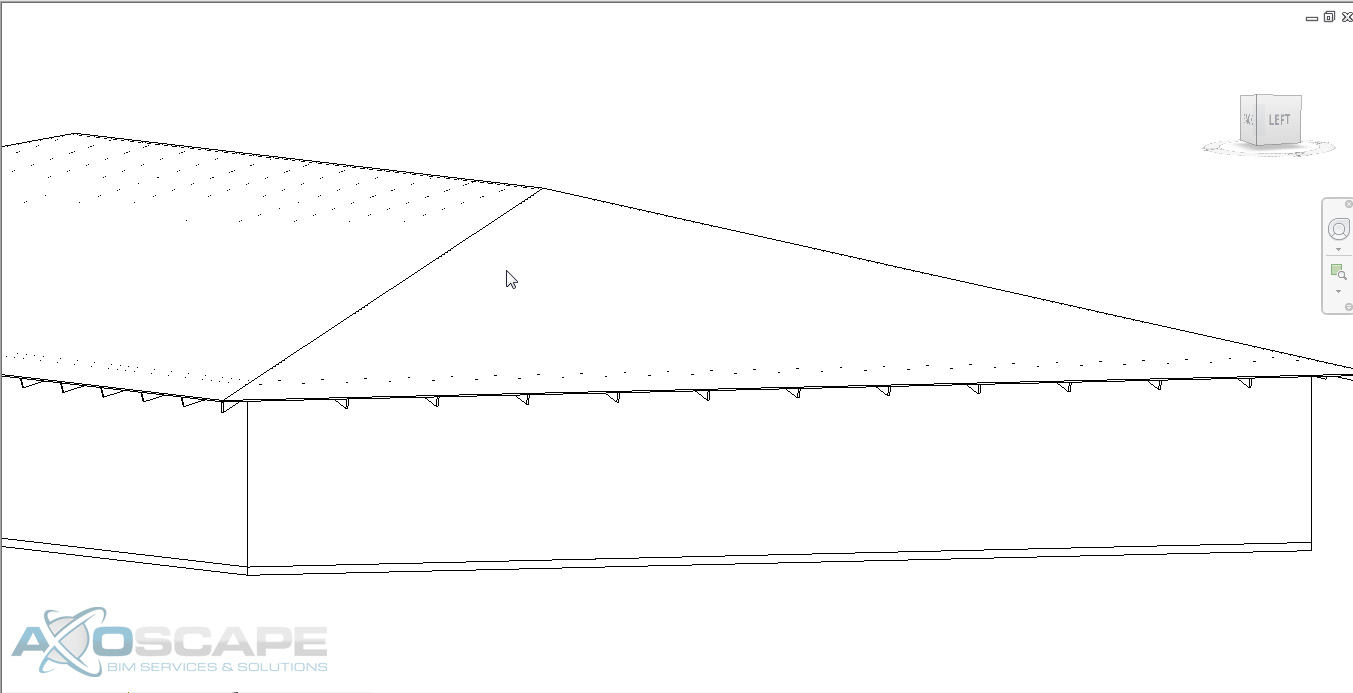
 ⦁ Use the extrusion tool to create the web of the truss in two separate pieces. Center the web around the reference line and dimension the width of the web.
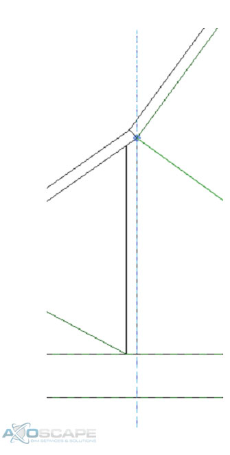
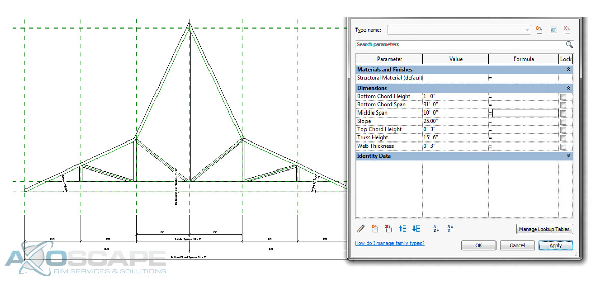
 ⦁ Test to make sure everything works accordingly.
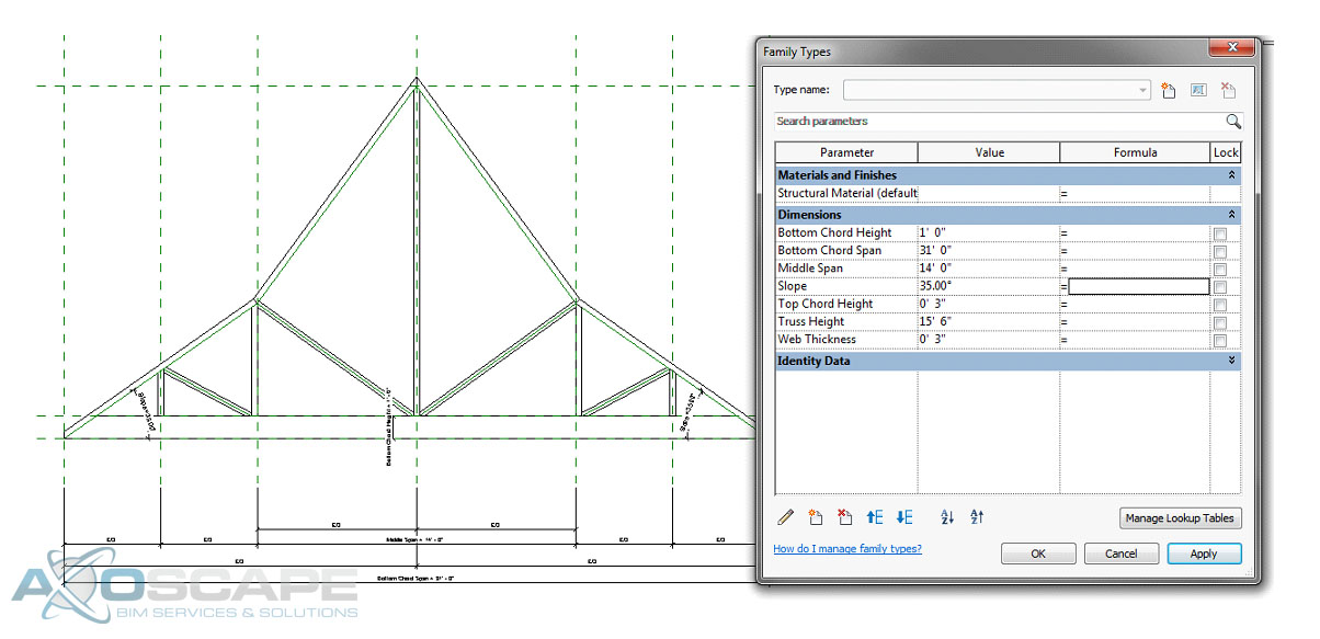
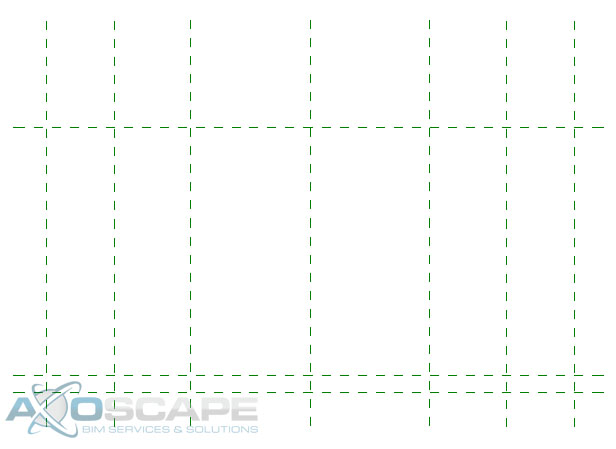
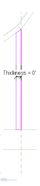
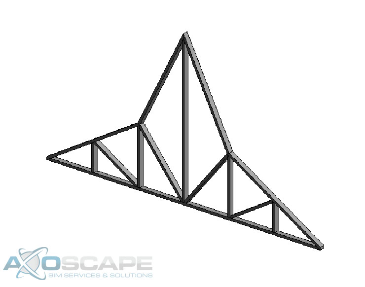
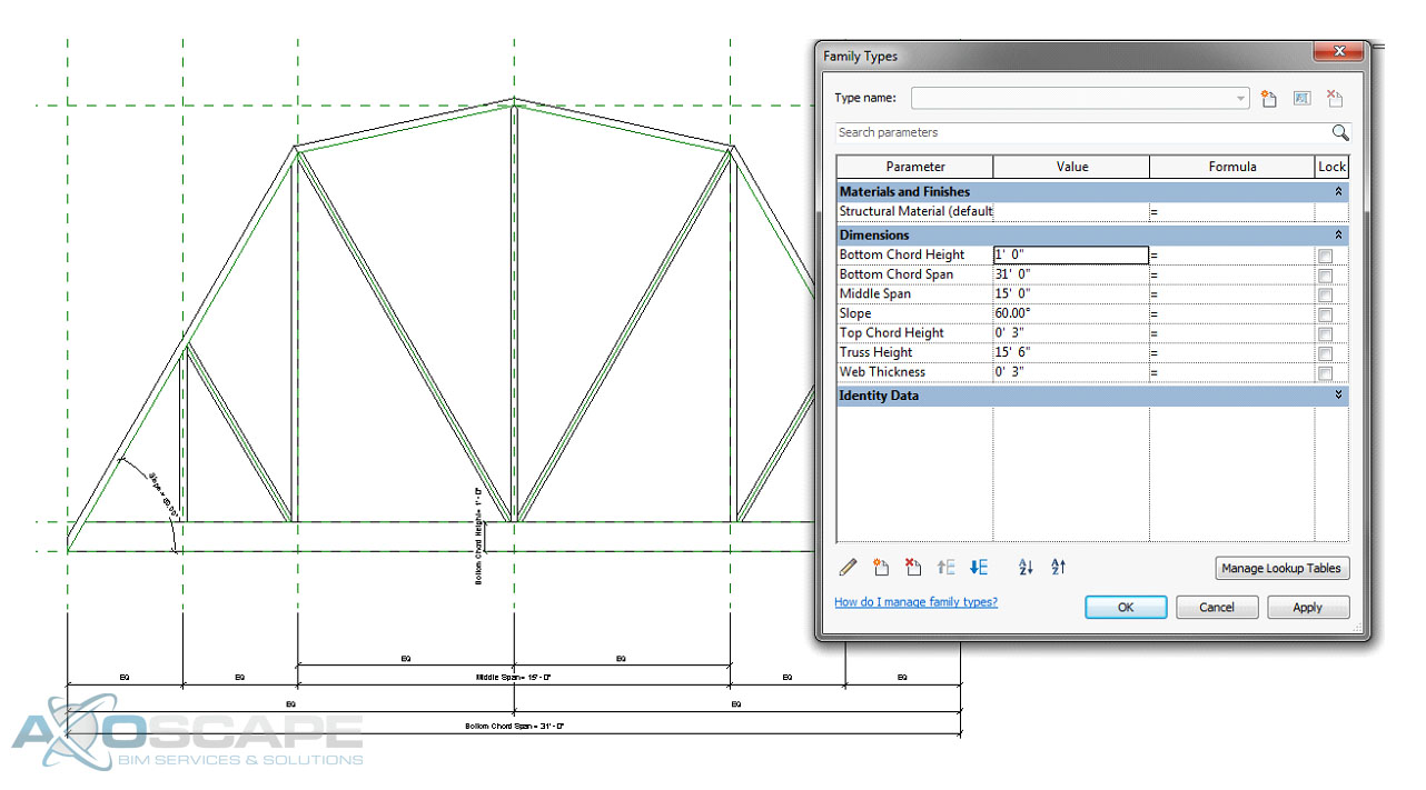 ⦁ Open up the left elevation and create a reference plane for the thickness of the truss and align extrusions to the reference plane. Then test to make sure everything works like its suppose to.
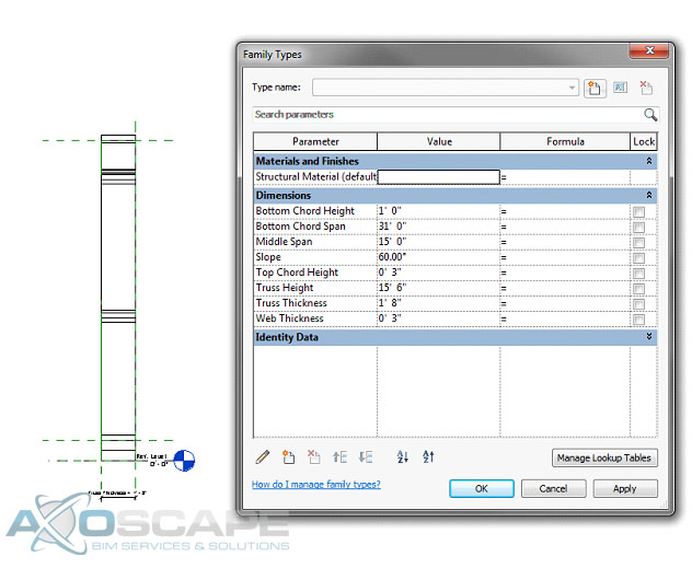
