Everything in this world has an origin, a starting point, including Revit. The origin point is useful in many ways to us, especially when there’s collaboration involve with a handful of users with multiple models in one project. It allows the user the ability to line up the models in various ways to make the modeling and noting process to run smoothly. Having the origin helps to coordinate with others a bit smoother, but it’s crucial to know how the models were built in order to link in Revit correctly. It’s just as important to know how to export the models as well in order to share the files from one user to another.
The difference between linking models based off of the origin point, and also linking them based off of shared coordinates.
How to set up a file with shared coordinates.
How to export each method.
There are two different ways to link in Revit models into projects. Through shared coordinates and also origin to origin. The difference between the two is based on how the origin point is set up. When linking in a model through origin to origin, this is telling the model to use the same origin point as the reference point to line up both models. But when the user links in a model based on shared coordinates, it takes the origin point of one model and uses it as its own.
Setting up shared coordinates is a fairly simple process to go through. It may seem a bit complex at the thought of it but it’s really simple.
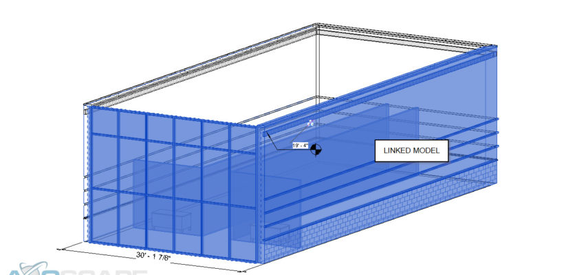
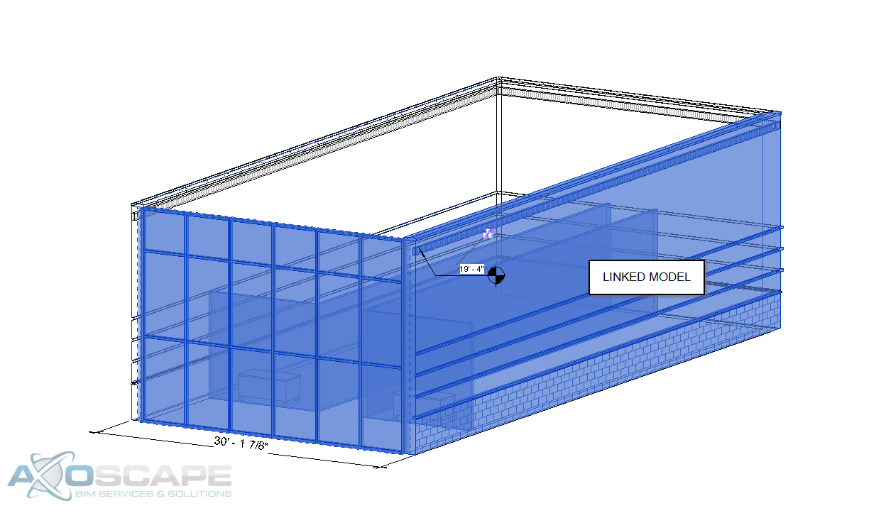
The image above contains a linked Revit file placed in at origin to origin. This will be the starting point for the shared coordinates process. One thing that will have to be verified by the user is the elevation. Some models might be slightly off axis. All that needs to be done to correct this is open an elevation/section view and line up the levels if need be. Once this alignment is done, the next portion that will have to get aligned is in a plan view.
Once everything is lined up the way it needs to be, click on the Managetab, select the drop-down arrow underneath “Coordinates”, and click on “Publish Coordinates”. By doing this, it’s telling the file this is your new reference point.
Once the coordinates are published to the model, the file will have to be saved in order for it to retain those coordinates. There are two ways to save the coordinates.
1. By saving the file where the model(s) are pulling the coordinates from. This will prompt a window informing the user that it’s about to save those coordinates onto the file.
Click save and continue saving the project. Here’s a rule of thumb when it comes to this portion of the saving process. The file with the updated coordinates will need to be closed out in order for the coordinates to be saved onto the file, or else it will send an error message explaining why it’s not able to save the coordinates.
2. Saving the file through Manage links. I would recommend this when there are multiple models involved. Select the file(s) and at the bottom left-hand corner there’s an option to “Save Positions”. Click on that and the same save window will be prompt as it did on the first option.
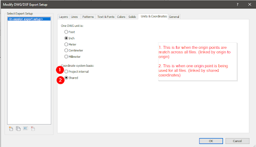
There’s a difference when exporting each model. Similar to how each model is linked into the project there’s a slight difference in how it’s exported as well. See below.
The most crucial part when it comes to exporting is selecting the coordinate system basis.
If the coordinate system basis is not set up correctly, then the model when linked into Navisworks, Revit, or AutoCAD will be floating out in the middle of nowhere.
I hope this was very informative, but just to recap on everything that we went over. The difference between origin point and shared coordinates. How to set up shared coordinate system. Last but not least how to export both methods out to a dwg format.
A Child’s Hope now has 10 orphaned children living in our home in La Montaigne Haiti and is continuing to provide lunch and support the education of three hundred children at the nearby school.
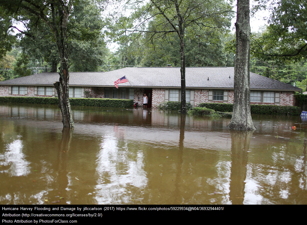
We are pleased to announce that we will be presenting a session at AU Las Vegas 2018 (Nov. 13-15) called Using Reality Capture to Help with Hurricane Harvey Relief Efforts.
A Child’s Hope is a community in Haiti committed to giving lost and abandoned children a home, a hope, and a future. Axoscape was involved with the original design of the orphanage and led several community-based design charrettes that involved Studio RED Architects as well as architecture students from University of Houston.
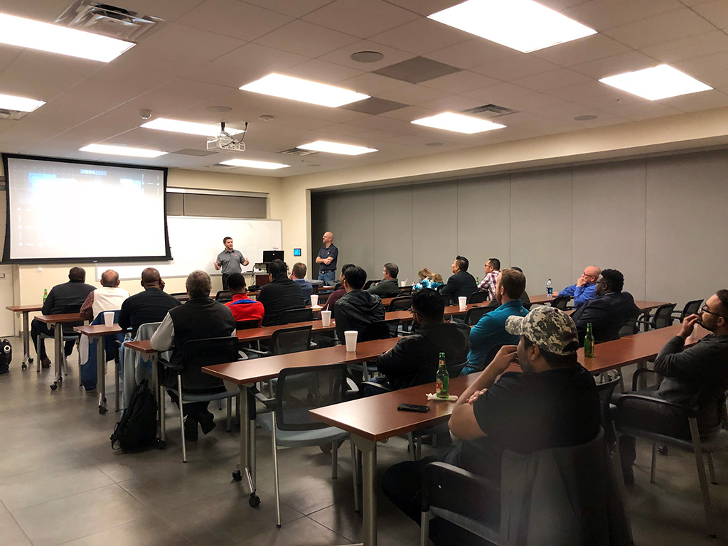
Be part of a local community of Revit and BIM application users that range from beginner to expert skill levels. Get the most out of your software with access to our knowledge network. Since 2002, BIMMeet (formerly Houston Area Revit Users Group @HARUG) has been the main resource in the area for Revit Users, AutoCAD Architecture, AutoCAD and other BIM related tools.
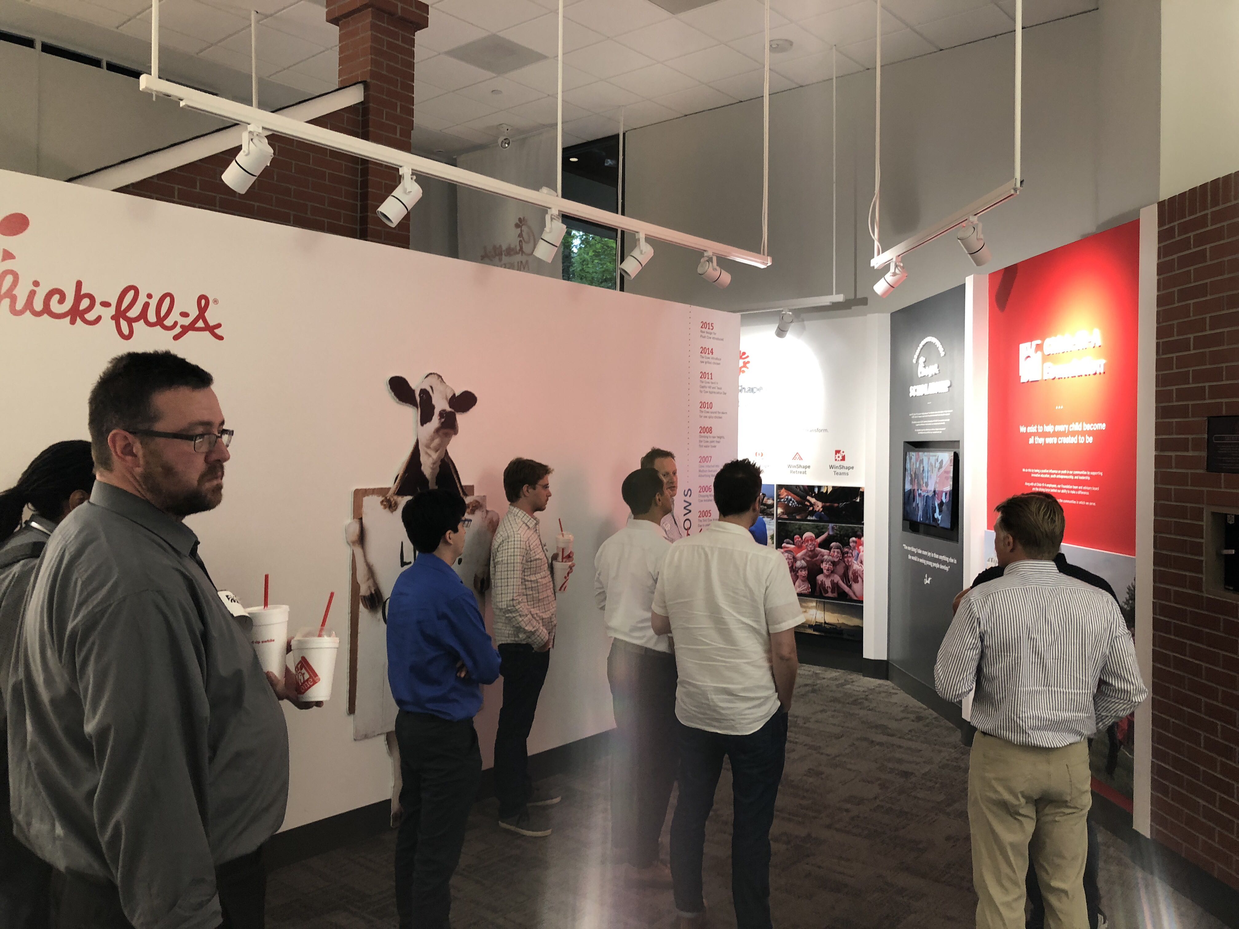
Axoscape debut’s the VR backpack at Chick-fil-A headquarters as part of an internal building technology showcase featuring prefab mockup, Plug-n-play LED Lights, Augmented Reality, BIM, and Virtual Reality.
As a Revit user when starting off a project, the Project Coordinator will distribute some files to link into your model as a starting point. They will typically send out dwg, RVT, and/ or NWD files. There is always a project that will throw a curveball to the project. One of the biggest curveballs anyone can get hit with is working with a new file type. In this case, I will be discussing some differences from working with prototypical file types versus something like an IFC and a NWD.
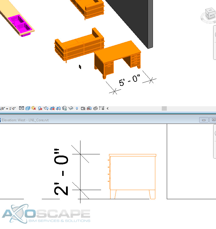
In most cases, an RVT file would be the ideal format to work with since Revit understands it completely. Dimensions strings and elevation tags are a few of the annotation features a Revit user will be able to use on a linked RVT file.
Another great feature the user has when linking another Revit model is the align command. This is very crucial when lining things up with another model. Reason being is the fact that the user is able to select the component. Having this ability helps to review some of the parameters from this file.
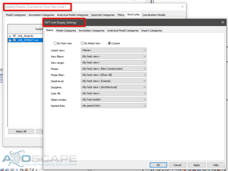
The best part about linking another Revit file into a project is having the ability to schedule out everything from the project. Since it only contains Revit components the schedules will be 100% smart. Visibility graphics can override components within Revit, which means the linked RVT file will be affected as well. BUT it also has its own visibility settings in case the user doesn’t want to change a few components of the project.
DWG’s are the next typical file type to link onto a project. This file type limits the user on some of the things that can be achieved. For instance, the ability to use the elevation tag. However, by creating a dimension string, the user will still be able to find out the height of something.
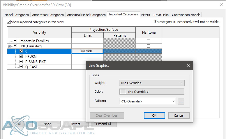
Aligning items to faces of a DWG is a plus when it comes to lining things up nicely especially when it is at an angle. The only thing that can be overridden on a DWG is the line weight, color, and the line type.
If a schedule is created to read all the furniture equipment in a project, it will be blank since Revit does not recognize DWG elements. However, there is the ability to insert blank rows and insert all the information for the DWG elements with the caveat of manual updates.
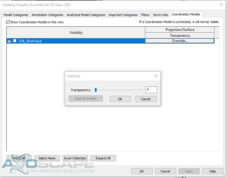
NWD’s limits the user on what they can and can’t do. From working with NWD’s, the idea behind it was having the ability to coordinate within Revit. With an NWD model, the user is not able to select any of the elements or even change the color, line type, nor the line style. The only thing that can be overridden is the transparency level.
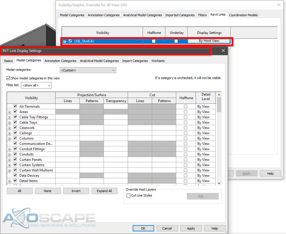
Now IFCs can be tricky to work with. Since IFC’s are typically produced from a sketchup model, all the elements are faces and not solids. Which means if the person that created the IFC model accidentally shifts a vertice on a face the whole face might not display correctly in Revit. This will cause problems when trying to align elements.
One good thing about IFC models is having the ability to override components similar to how the user would if they were working with another Revit model.
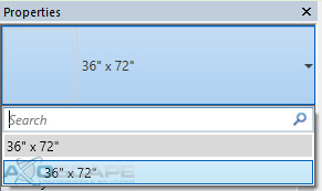
It is able to recognize all the different components. With IFC’s the user is able to copy and paste elements, BUT I wouldn’t recommend it since it will only load the copied elements from the IFC model. Here is an example of copying a window from an IFC model vs the window library in a project.
IFC Library
Revit Library
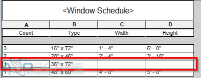
Another thing about copying the elements from an IFC model into the Revit file is if a schedule was created to read all the windows, the copied IFC windows will come out blank due to no size parameters.
If the IFC file is on Revit 2018, it will allow you to input the size in the window but it’s not 100% accurate due to the window not being a RFA (Revit family). Which means any size can be placed on the window but it will not reflect the physical model inside the file.
In conclusion, using a Revit file or an IFC model can be some of the best references. Since the IFC files act similar to how a Revit file is with the exception of a few parameters. DWG is the next best thing to work with, and if there’s any coordination involve with any MEP components. Or if the project is fairly large then I would use a NWD model to minimize the file size. Especially if it’s only to reference on the location of elements.
If you’re like most of us, we usually wait awhile before migrating to a later version for the following reasons:
It’s a one-way street with upgrading and since you can’t go back, we want to make absolutely sure.
It may take a while for consultants to get on board.
New releases often have some untested issues so best to wait until the dust settles and the first hotfix is released.
However, with the latest release of Revit 2019, we thought it would be a good idea to cover some of the more useful improvements since 2018. With all the dot releases in between, it’s easy to lose sight of the time-saving features that we may have missed.
Revit 2018 extends the power of global parameters, which help embed design intent in a model to also apply to radial and diameter dimensions and equality constraints.
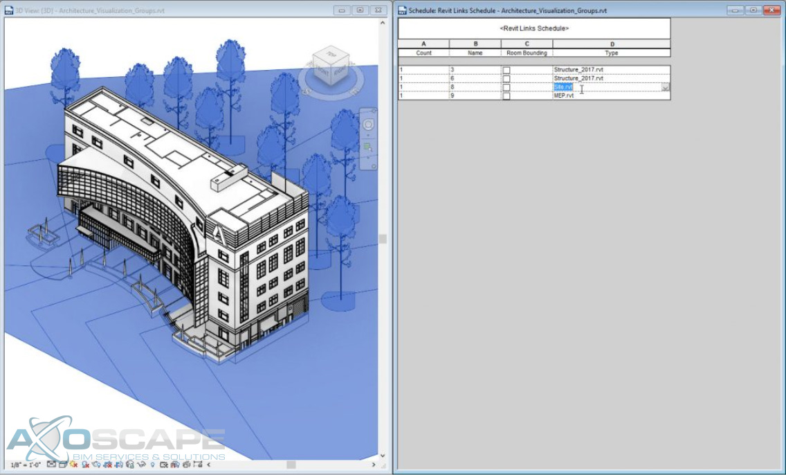
Revit 2018 now includes the ability to schedule and add parameters for links and groups, helping you to better understand and quantify a project.
Select Model Groups or Revit links as categories when creating a schedule
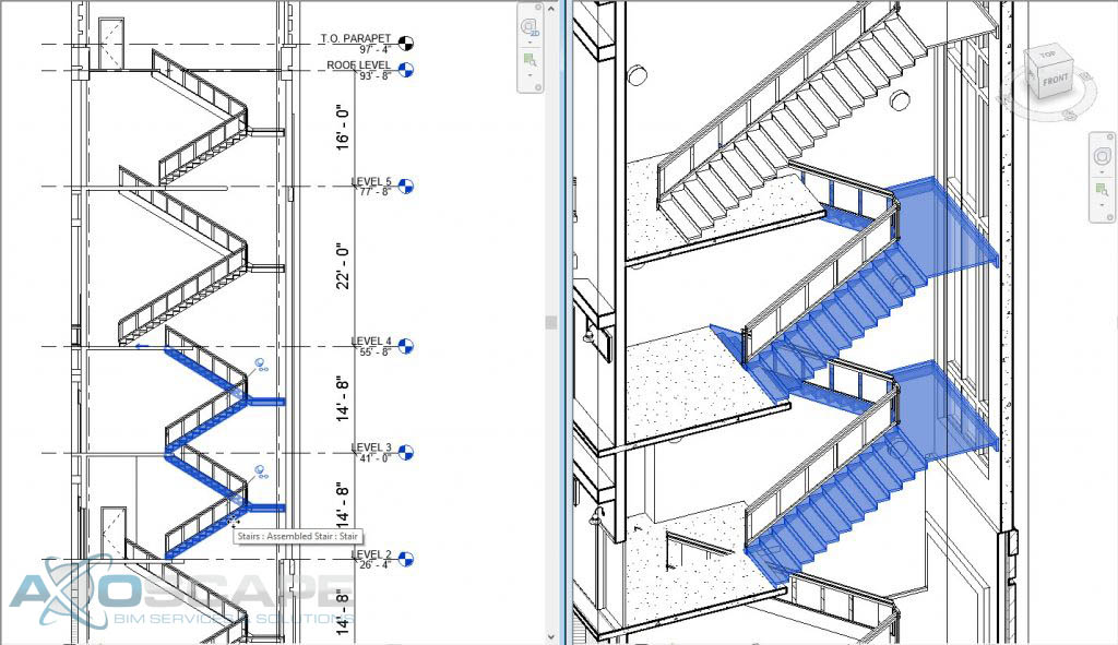
Revit 2018 introduces a new Multistory Stair object that enables faster and easier modeling of complex stair towers for buildings with many stories. By connecting stairs to the levels in a project, you can model one stair and expand it to the entire building. When levels of your building change, the stair will automatically update as well.
Add and edit stair towers in multi-story buildings
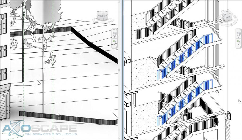
Further improving stair design for multi-story buildings, the railing tool enhancements let you add accompanying railings to an entire stair tower with one click and propagate edits from one instance to all in a group of similar stair runs. Beyond modeling railings associated with building staircases, with Revit 2018 you can also attach railings to topography to model fencing, road barriers, or outdoor handrails. This continues the work we did in 2017 and 2017.1 to make modeling railings easier and simpler.
Add railings to a stair tower with one click. Attach railings to topography to model fences or outdoor handrails.
The ability to model in perspective view released with Revit 2017.1 reduces the need to switch views to perform everyday modeling tasks and work in the view that best supports your workflow.
Revit 2018.1
The new schedule management in project browser feature — we know you’ve been asking for this schedule browser. This feature lets you apply project browser organization to schedules. Reducing visual clutter makes it easier to find schedules, especially in large projects.
Additional ready-to-use content delivered with Revit 2018.1 is especially helpful for new users and Revit LT subscribers wanting to get started fast. Content includes office cubicles, furniture, residential and commercial windows, and an appliance library. Download the content from the Autodesk Knowledge Network.
With the new Visual Materials API, you can create and edit Appearance Assets — the particular instances of classes representing visual material properties– of materials in Revit. Another top customer request, the opening of the materials API allows the automated creation of materials libraries and better transfer of material information between products. Now you can use any third party tool to make changes to material finishes.
Revit 2018.2
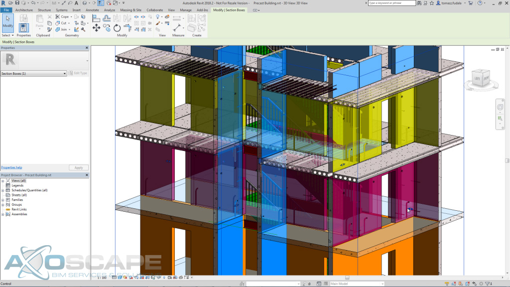
Improved Section box controls
We’ve improved section box grips (or controls) so that they are easier to select. This should make manipulating section box edge locations much easier and make it so that you don’t accidentally select something you did not want to.
Improved section box controls
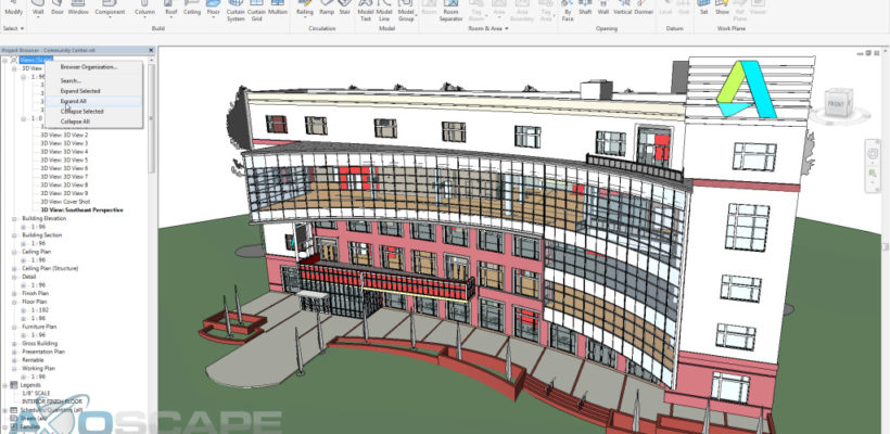
Project Browser Expand and Collapse
We’ve added new right-click menu options that allow you to expand or collapse everything in the project browser at once or just for the selected item in the tree.
Project browser expand and collapse
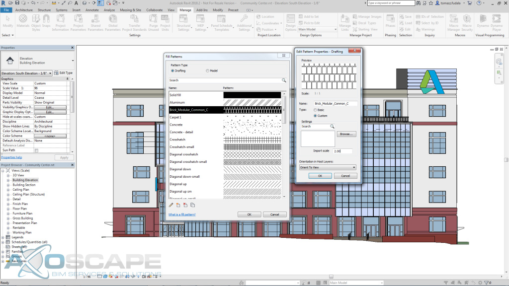
Improved Fill Pattern Dialog We’ve replaced the old fill pattern dialog with an updated dialog that has the solid fill pattern at the top of the dialog, the ability to search for patterns, allows for multi-selection, deletion of patterns, and is resizable (remembers its size). Finally, when you’re editing a pattern, the dialog allows you to scale the pattern without having to reload it (plus it automatically previews the scale change). These changes reflect a number of different requests and should make working with fill patterns easier.
Fill pattern dialog enhancements
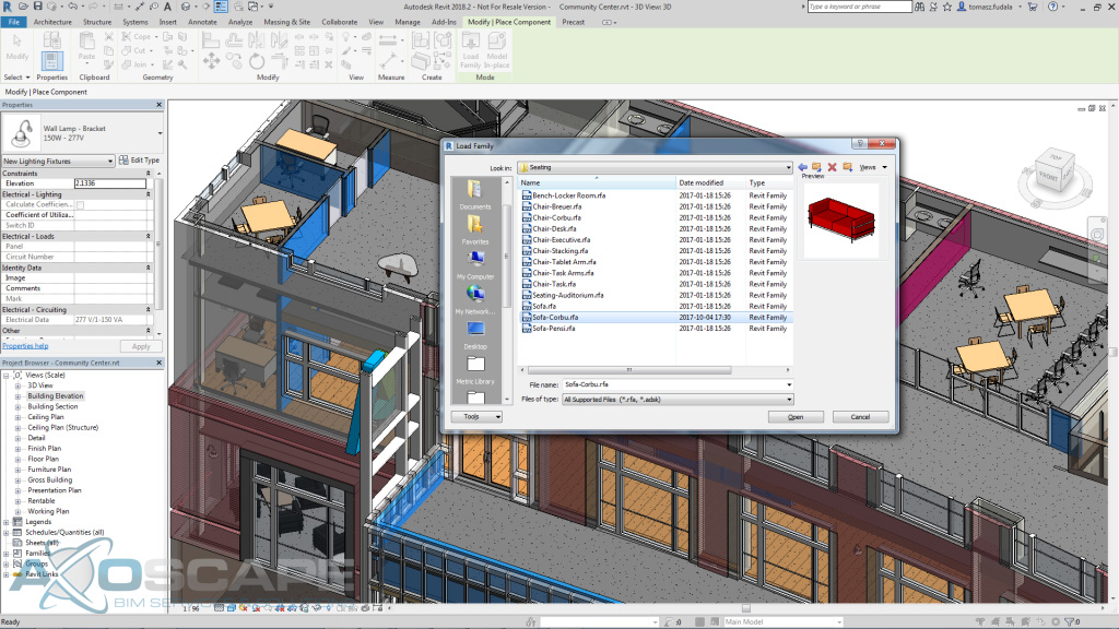
Remember the Last Location for Loading Families This enhancement remembers the last location from which you loaded a family the next time you go to load another family. This should make it easier to navigate to the location where your families are stored when working with them on a project.
Revit 2018.2 remembers the location of the last family loaded
Remember Column width spacing in Type properties dialog In what is really more of a fix than enhancement, we are bringing back the functionality that remembered the column widths of the family types dialog when editing families.
Revit 2018.3
Added connection to Next Gen BIM 360 for cloud worksharing, which allows flexible access permissions for cloud workshared models within the same project.
Updated the Scope Box drop-down list in the Properties Panel to display the scope boxes in alpha-numeric order.
Improved the pipe sizing feature by basing the size of a single pipe attached with taps or analytical pipe connections on the worst case.
Revit 2019
Many of the features new in Revit 2019 contribute to your ability to more efficiently and intuitively create information that captures design intent. With features to control view graphics, let you work in a more modern immersive 3D environment, and communicate better visually, Revit 2019 helps you do your core work.
Get greater control overview graphics with “or” in filters
The variable “or” to view filters gives you greater control overview graphics by being able to create view filters with multiple rules and nested sets with the combination of AND and OR conditions.
Make the most of your working space with tabbed views & multimonitor support
Recognizing that you work with multiple views open at once and are looking for better ways to manage them, new Tabbed Views in Revit 2019 deliver a more modern experience that lets you maximize your working space. You can arrange and organize views exactly as you wish, and easily see which views are open at a glance.
Now you can drag views out of the Revit application window to secondary monitors, dramatically adding to your options for increasing and managing your working space.
Experience immersive design — do more of your modeling in 3D
Revit includes a few features that make it easier to create geometry and work in 3D views. With new Levels in 3D views, you can display and edit levels in any view, including orthographic and perspective 3D views, reducing the need to switch to 2D views to orient in a model.
You can work easier and faster with new full-screen uncropped perspective views that provide a more immersive experience when viewing and working within a model. Save time by easily toggling between default 3D and perspective views and moving around either view freely with navigation commands such as Zoom, Pan, and Orbit. Scope box improvements provide more consistent behavior of levels across 2D and 3D views, further improving the experience of modeling in 3D views. Scope boxes can be assigned to 3D views and they sort alphabetically.
Communicate design intent with more complex fill patterns and more life-like renderings
With new double-fill patterns, you can easily create more complex graphical renditions by applying both foreground and background fill patterns to materials and filled regions. You can use double-fill patterns on filled regions, visibility/graphics display overrides, object level overrides and for both projection and cut settings of materials.
Split railings
Use the Split tool on railing elements outside of the sketch mode and get more control of railings generated from the railing path. Simplify the creation and modification of railings using the split tool to split railings with one click. When a railing is split, the resulting elements have path sketches independent of each other.
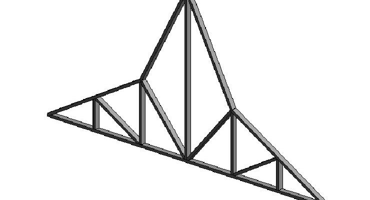
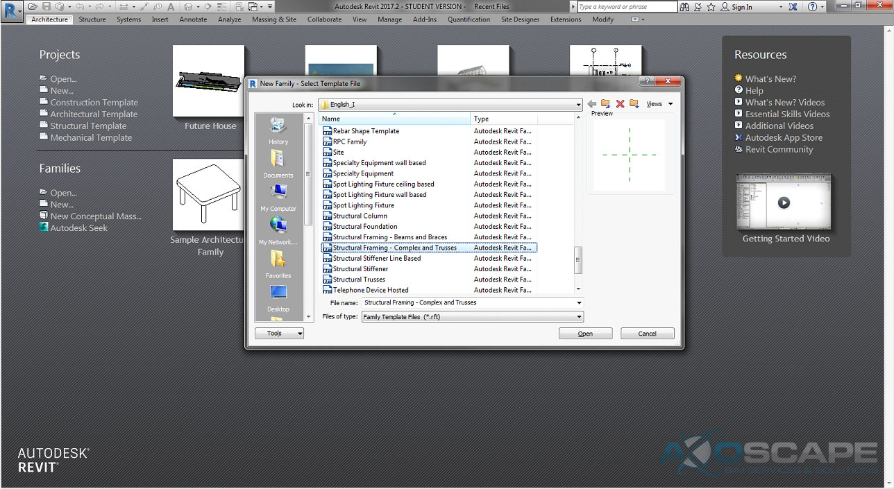
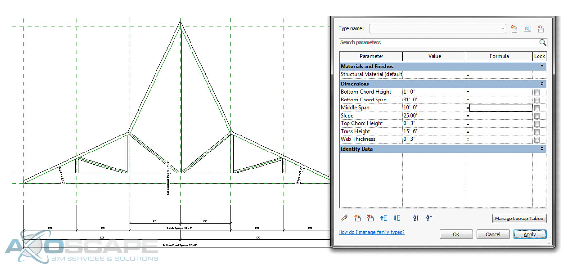
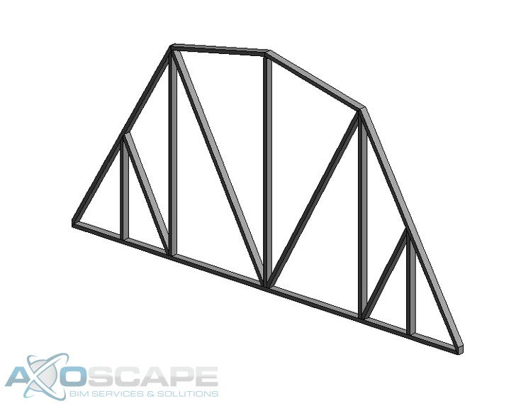
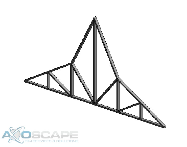
When creating this type of family you can make both a Polynesian and a Gambrel roof truss with this one model. It can be tricky to create this family, but in the end, it could save you time once this family is finished.
⦁ Open up Revit and create a new Structural Framing – Complex and Trusses
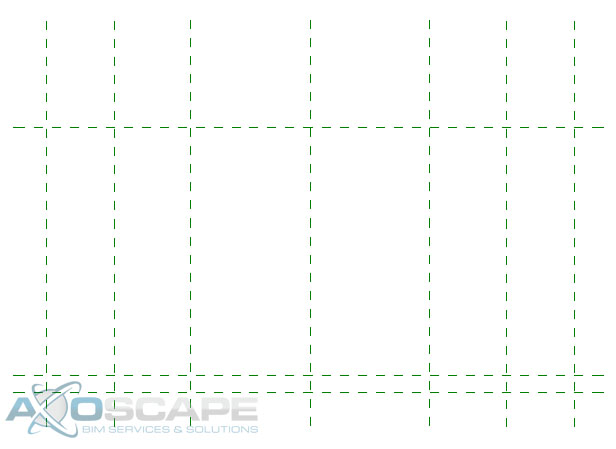
⦁ Open up the front elevation and hide the level in visual graphic (VG).
⦁ Create three vertical Reference plans on each side of the center axis.
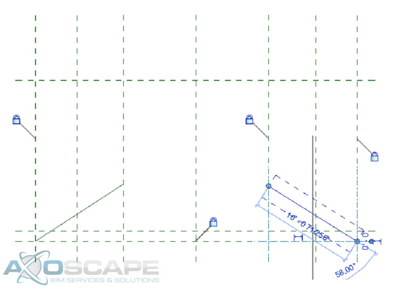
⦁ Create two diagonal reference lines to create the slope of the top chord of the truss.
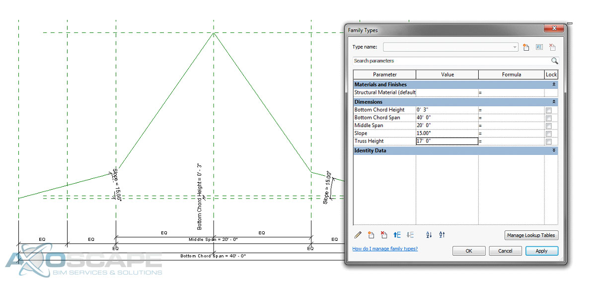
⦁ Add a dimension parameter for the bottom chord span and lock the parameter then equal space between the overhangs with a dimension.
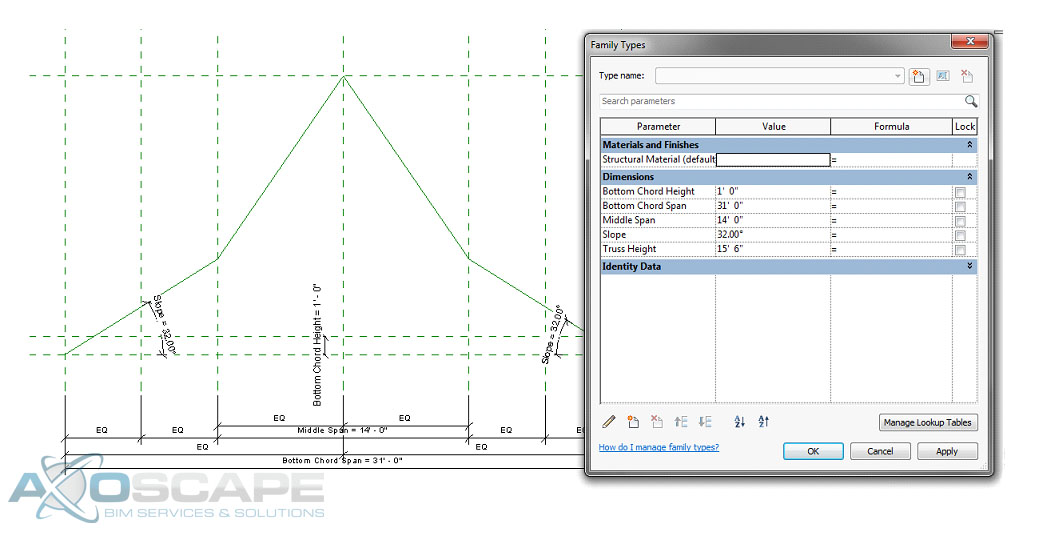
⦁ Add a dimension parameter for the middle span and lock it, then test to see if reference planes change.
⦁ Add an angle dimension parameter to each slope and lock it.
⦁ Add a reference plan for the top of the bottom chord and add a dimension parameter for the height of the bottom chord.
⦁ Add a reference plane at the top of the truss and add a dimension parameter for the truss height.
⦁ Test to make sure things are working correctly.
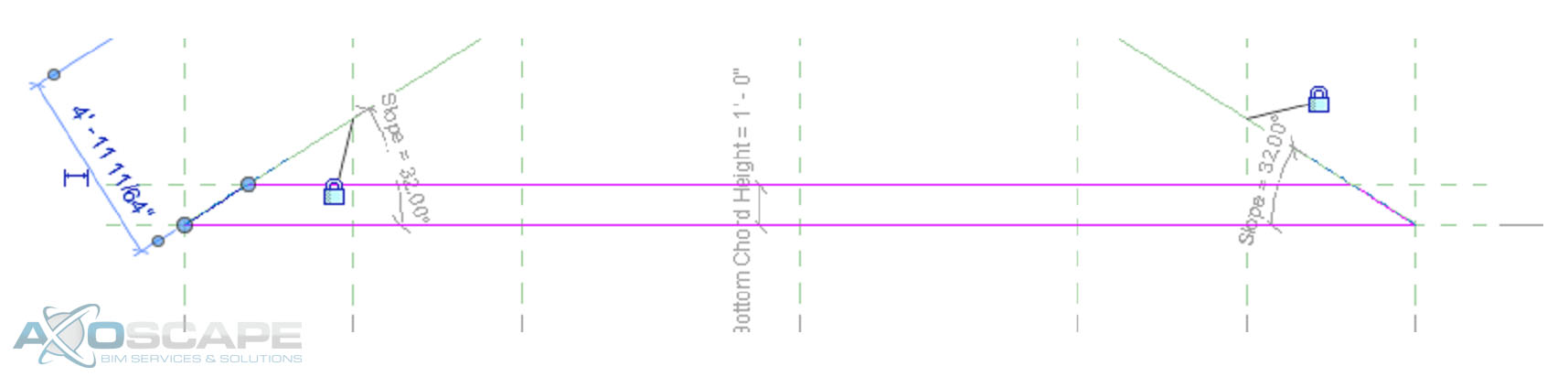
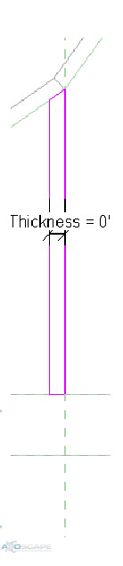
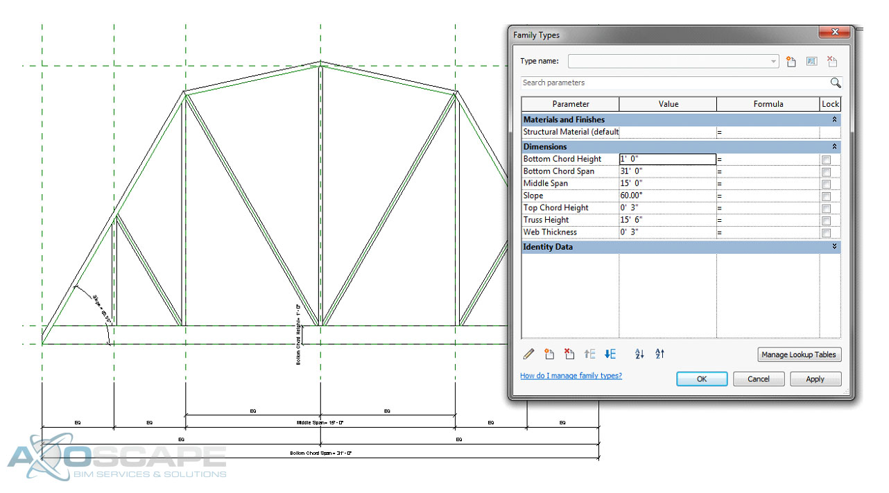
⦁ Using the extrusion tool create the bottom chord span by using the pick lines and trimming to get the shape, also lock the lines to the reference planes.
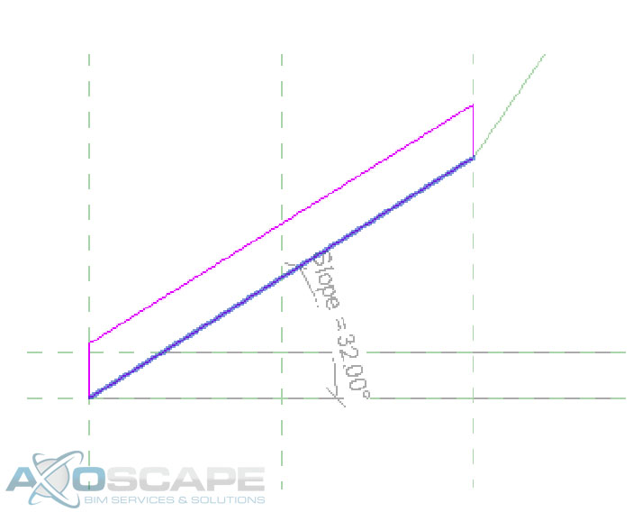
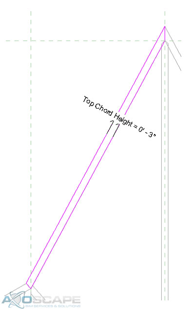
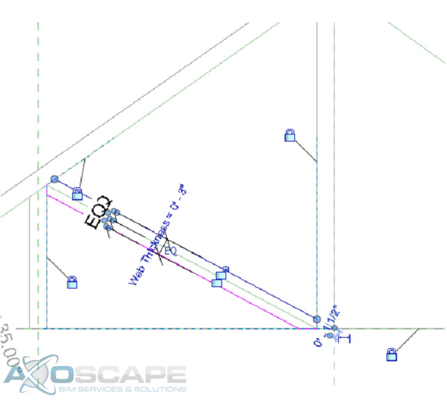
⦁ Do the same thing to create the top chords for each side, also add a dimension to control the height of the top chord and make sure you lock it to the reference line. ⦁ Extrude the webs on each side by using the two vertical reference planes on each side, also add a dimension parameter for the web thickness.⦁ Use the extrude tool make middle web member the same way.⦁ Test to make sure things are working correctly.
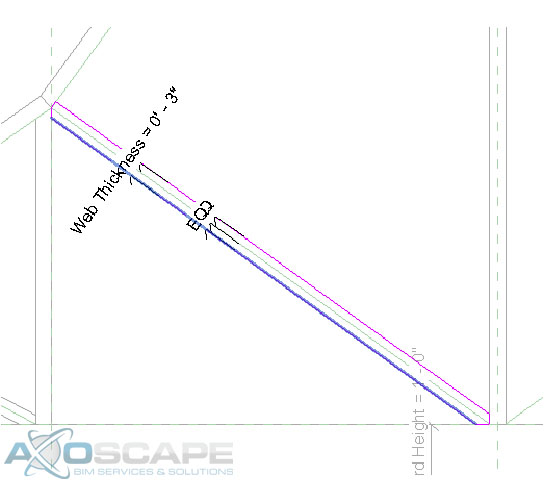
⦁ Add reference lines for the webs to each side and lock it to the top and bottom chords. Then test for function.⦁ Use the extrusion tool to create the web of the truss in two separate pieces. Center the web around the reference line and dimension the width of the web.⦁ Test to make sure everything works accordingly. ⦁ Open up the left elevation and create a reference plane for the thickness of the truss and align extrusions to the reference plane. Then test to make sure everything works like its suppose to.
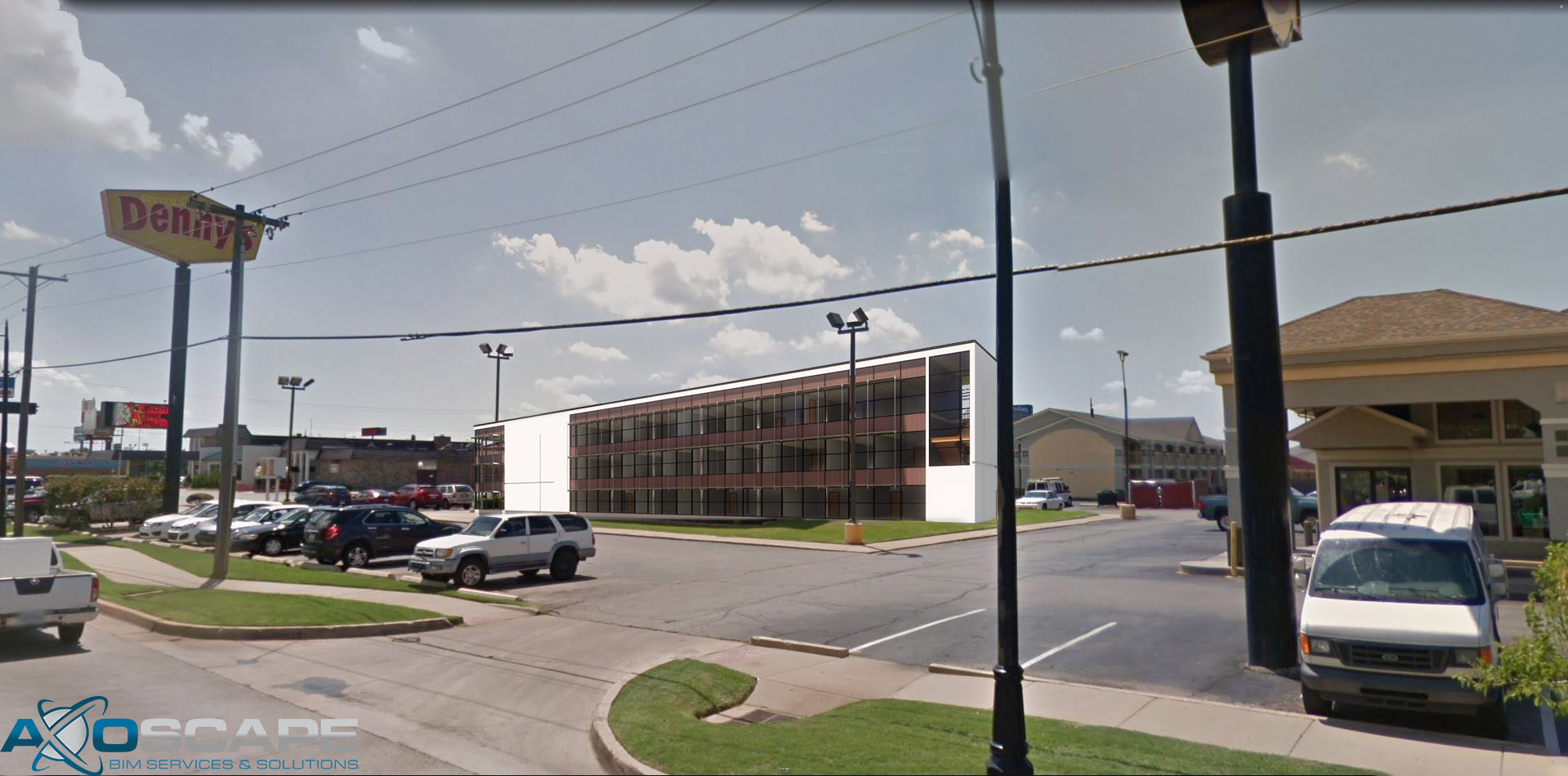
In this article, we’ll be going over how to camera match the perspective of an image using Enscape. This workflow should allow you to much more reliably camera match an Enscape building to an existing photo.
I want to note that I will not be diving too deep into Photoshop techniques in this article. The focus will be on how to match the perspective to Enscape’s camera and how to export images required for a superimposing workflow.
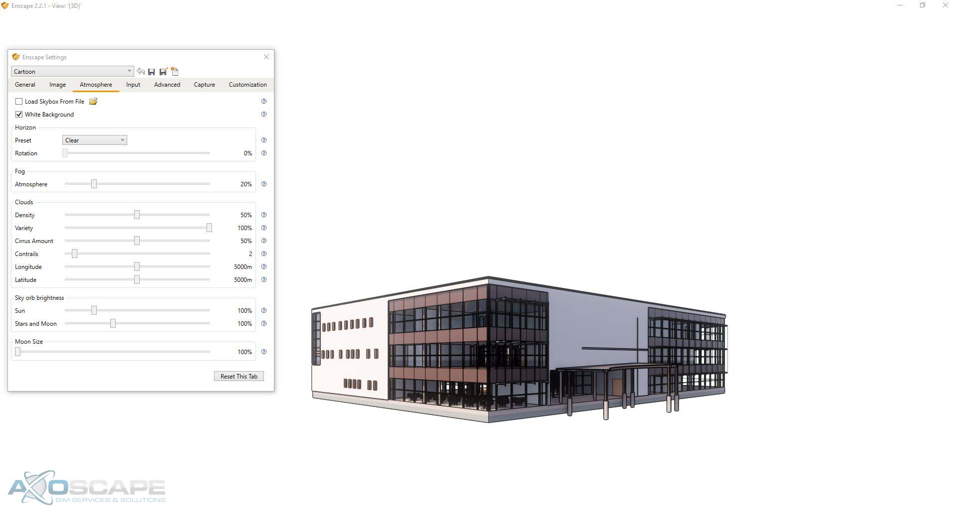
Before loading Enscape, I recommend creating a separate 3D view in Revit, hiding all elements and items that are not building related. The goal here to have the building completely isolated.
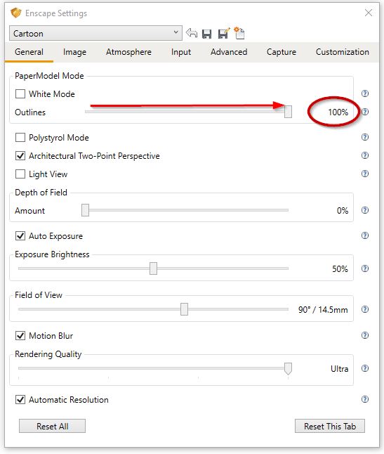
Here are the settings I used in order to completely remove any non-essential Enscape items from the scene.
Also, it is extremely helpful for the purposes of perspective camera matching that outlines be at 100%. This will provide a clear outline of your building.
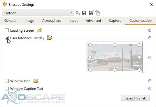
In order to begin camera matching. We’ll be taking advantage of Enscape’s User Interface Overlay feature in the Customization tab in the settings. But before we can use any image as an overlay, the image will have to be modified in order for it to be semi-transparent.
Load the background image into photoshop.
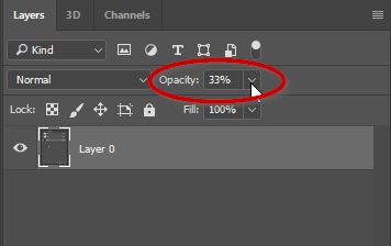
Unlock the layer by simply clicking on the lock icon in the background layer.
Once the layer has been unlocked, adjust the opacity slider to around 30%.
Your image should look like mine above. Where there is a checkerboard pattern brought through the image. The checkerboard won’t be apart of the image, it only serves as a visual representation of how transparent an image is.
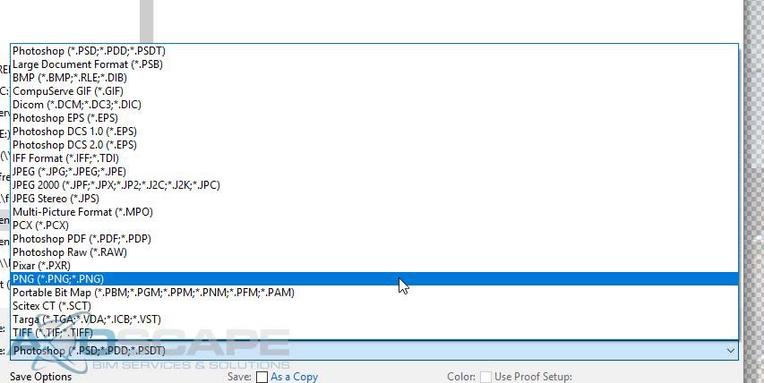
Now all that’s left is to save the file…
IMPORTANT
The file must be saved as a PNG for this to work. Do not save this as a jpg or the transparency data will be lost.
Now back in Enscape, return to the customization tab under “Enscape Settings” and click on the checkbox next to the “User Interface Overlay”. Now click on the folder icon and select the background PNG image we just created earlier.
The Enscape viewport should look similar to the animated GIF above. Where a fixed non-moving transparent image is overlayed the 3D Enscape scene. Start navigating around the building until the building angle’s line up with the photograph. Once finished go back to “Enscape settings” and uncheck the “User Interface Overlay”.
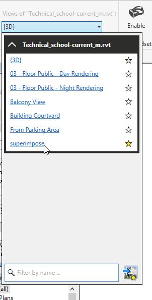
Once the perspective matches the photo. I strongly recommend saving your camera’s view by creating a view to save your Enscape camera settings.
It is equally important to lock that 3d View So there are no accidental camera adjustments in Revit.
This should act as a save point that you can return to in case of any camera movements.
The next step is to edit your settings for an optimal image. If there are accidental camera movements you can return to your previously saved perspective by selecting it in the Enscape Active Document rolldown menu.
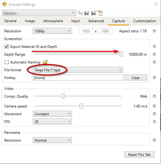
All that is left to do is to export the building image from Enscape into Photoshop.
Exporting the images is a 2 step process. In the Capture tab of the Enscape Settings. Click on the Export Material-ID and Depth checkbox so Enscape produces an image that can be used as an alpha channel. It is important to push the Depth Range all the way to the right in order for this to work correctly. I like using the Targa file format when dealing with images that are about to be processed. PNG could be used as well but old graphic design habits die hard.
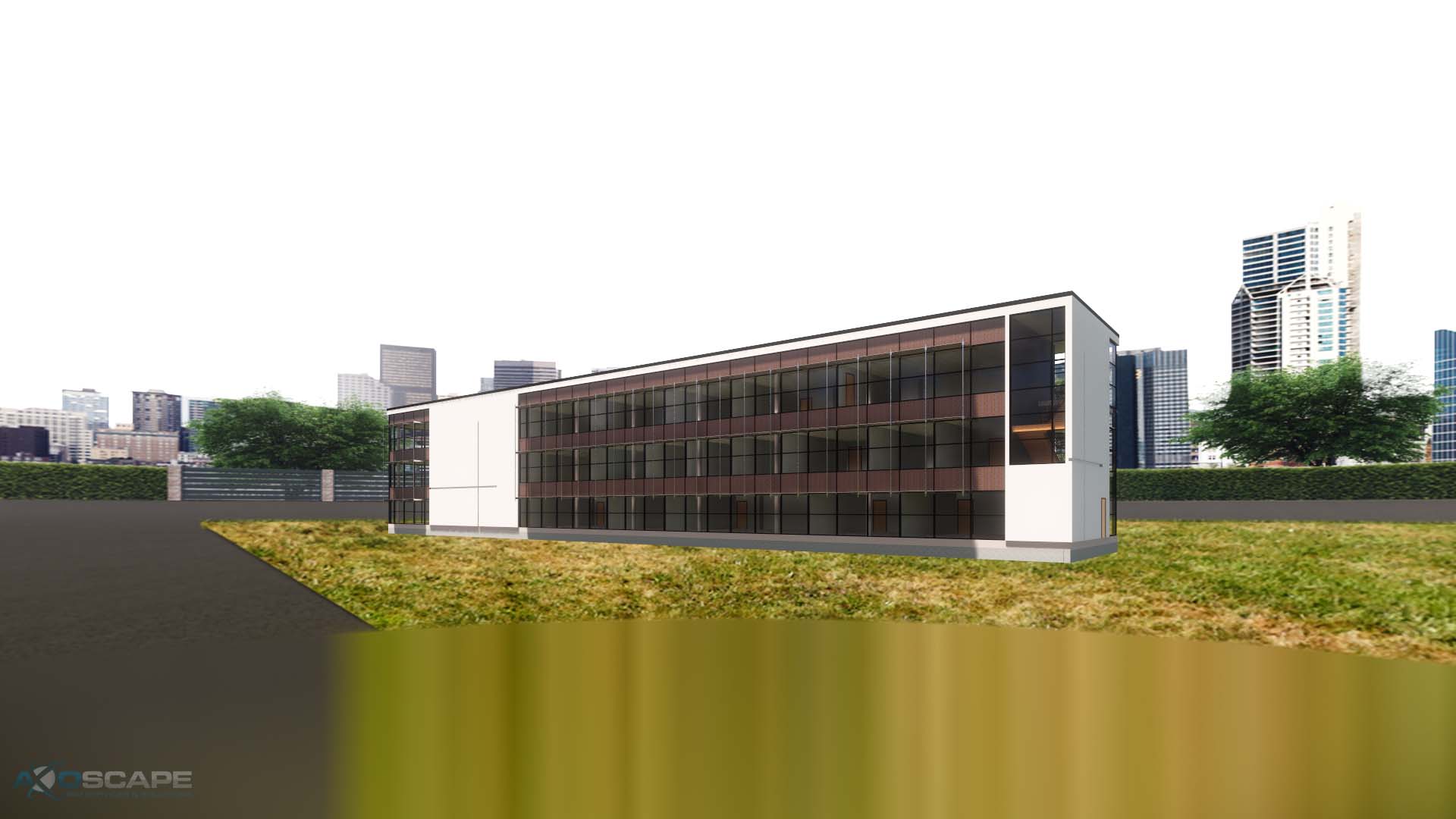
Exporting should produce two images. One is of the building & the alpha channel map.
At the end of this workflow, you should have 2 Enscape images that fit the perspective of another photo that are ready for superimposing.


 ⦁ Extrude the webs on each side by using the two vertical reference planes on each side, also add a dimension parameter for the web thickness.
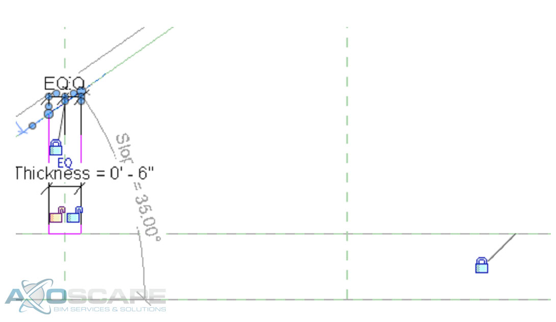
 ⦁ Use the extrude tool make middle web member the same way.
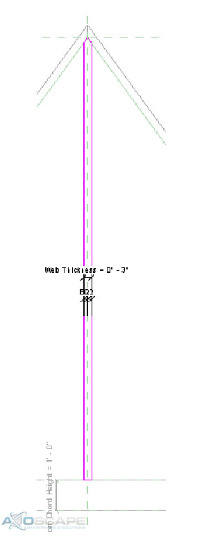 ⦁ Test to make sure things are working correctly.
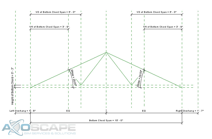 ⦁ Use the extrusion tool to create the web of the truss in two separate pieces. Center the web around the reference line and dimension the width of the web.
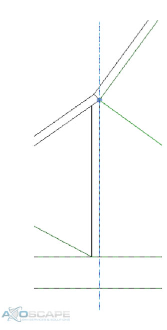
 ⦁ Test to make sure everything works accordingly.
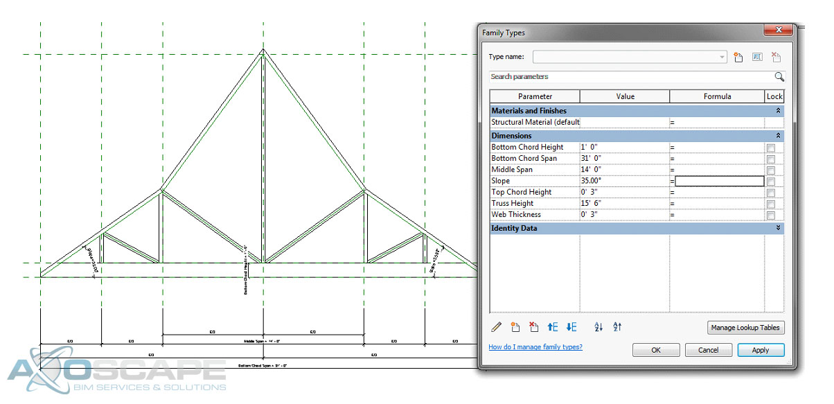
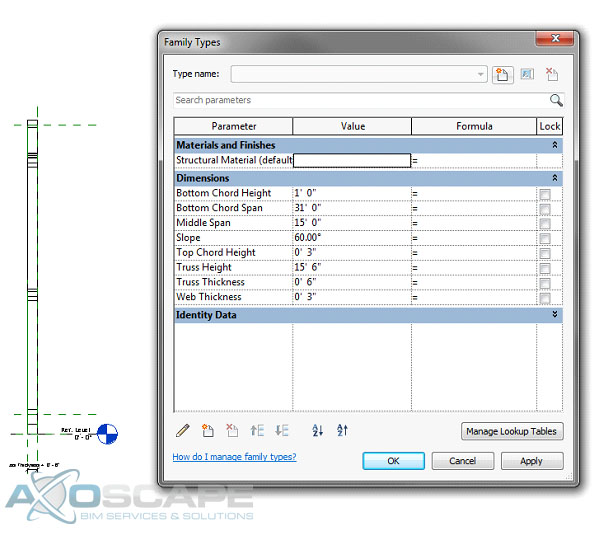
 ⦁ Open up the left elevation and create a reference plane for the thickness of the truss and align extrusions to the reference plane. Then test to make sure everything works like its suppose to.
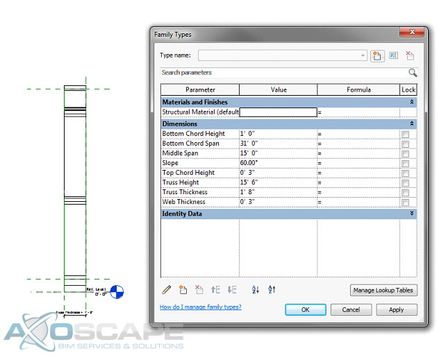


