It seems like disaster strikes at the most inopportune time: While working on an important project, right before an important deadline, when you are doing multiple things at once. We have scanned the internet and could not find an up-to-date, article that addresses these issues in one place so here you go. This article will help you minimize wasting time and effort not to mention frustration when Revit crashes occur. We will discuss why Revit crashes in the first place, along with preemptive measure you can take to keep things at bay, and finally what to do when the “blue screen” of death occurs.
Why Revit crashes?
A bit of history concerning system recommendations. Throw the recommended specs out the window since they do not help (they do not address the types of projects you are working on and your specific demand for resources). Here are some rules of thumb that may help determine if your system is up to snuff:
RAM (File size and compression (20x rule))
You may have heard of the 20x rule: Take your Revit project file size and multiply by 20, this is how much RAM you need just to run the current Revit session (not including all of the other background tasks you may have going on).
i.e. 100mb file x 20 = 2gb of RAM required
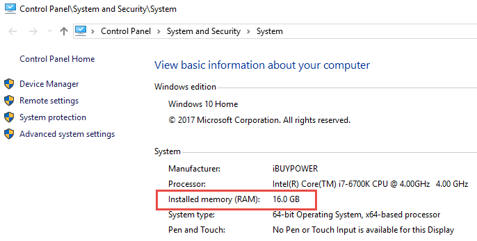
And do not forget the Linked File Sizes. You will need to multiply these by 20 as well since they all have to be loaded. It is no wonder you need to max out RAM. We recommend a 16gb minimum.
Hard Drives and Disk Storage (Virtual Memory)
So what happens when your computer runs out of RAM? It starts paging to the hard drive; however, if your computer is set to default settings, it may not meet the demand fast enough and things will come to a screeching halt.
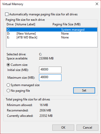
To prepare for this, do not let windows manage your page file size (those settings are for surfing the net and word processing, not demanding BIM Applications such as Revit and Navisworks and 3dsMax and Photoshop and Sketchup… etc.). Consult with IT before making changes to your PC if you are not comfortable doing so.
Set your Cache and Paging Size to three times the RAM (3x RAM)
i.e. 16gb RAM = 48gb page file size. If you do not have this, 32gb may suffice. Otherwise, get a new hard drive, they are cheap these days or opt for a speedier SSD which will improve overall performance as Revit is disk-write happy.
Quit unneeded applications:
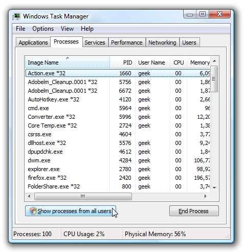
Sure it is nice to have that music video streaming in the background while you are working but not while you are opening a 500mb aggregate Revit file(s). Use the windows task manager (right-click on the windows taskbar) to see what is running and quit those other memory / CPU hogs:
Corrupt files or objects
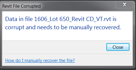
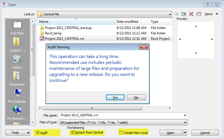
No one knows how this happens, it could be related to a corrupt family (see below) or a hiccup while syncing to central. The next time you open that file, click the “audit” option and be prepared to wait a bit longer than usual, however, it is a good way to identify issues before they get out of hand. That and some good ‘ol weekly Revit maintenance procedures such as purging items and keeping an eye on file size could be in order.
Corrupt family
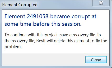
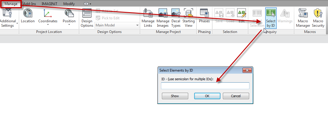
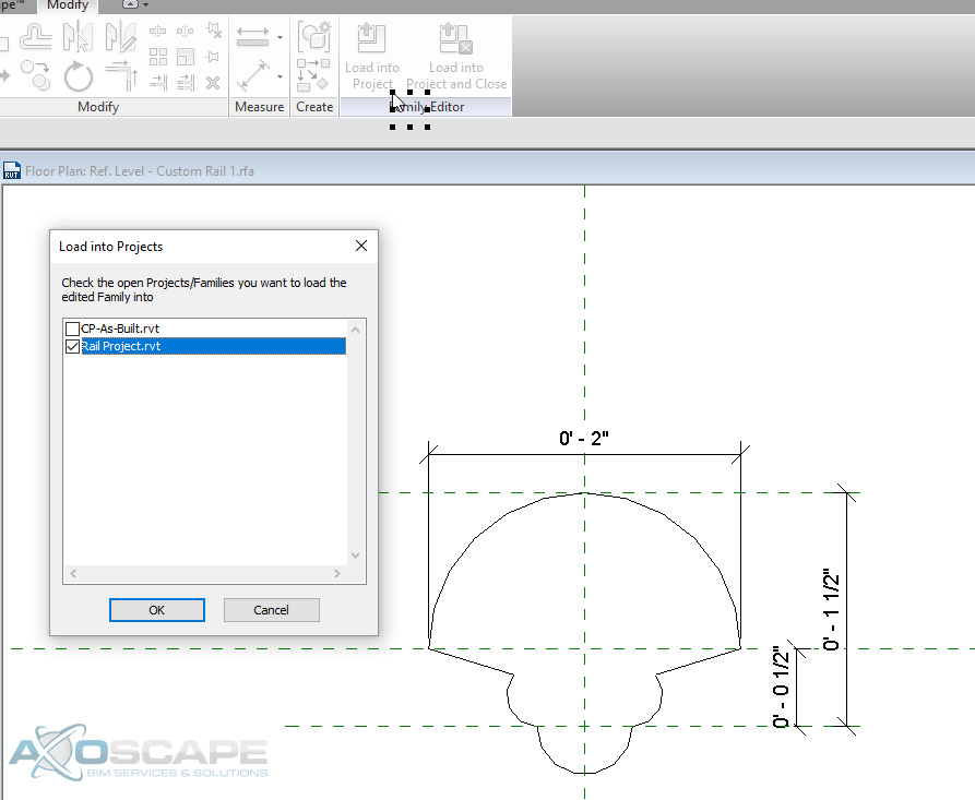
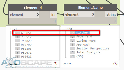
Just downloaded that awesome Revit family? It’s not so awesome now that it’s making things crash left and right. It could be that there are too many formulas or the hyperlinks exceed 256 characters or a number of items. When this happens, see if you can single out the culprit via element ID and modify it or get rid of it altogether (Oh and choose a more worthy source of downloading Revit families will ya? 🙂
Revit bugs
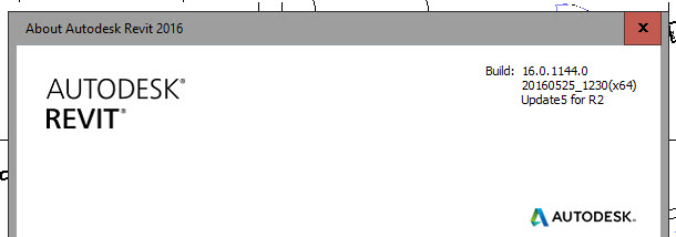
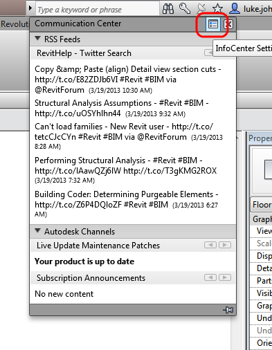
I know, I know.. Software is perfect and shipped bug-free right? In the “unlikely” event that you’ve come across a bug, I’m sure the software mfg would like for you to report it however if you are going to call support, you had better be on the latest version as that is the first question that the telephone operator is trained to ask. Identify your version by going to the help menu.. About; and/or check the InfoCenter to see if there are updates (it’s that satellite icon thingy, however, you may want to go directly to the Autodesk site just to make sure, and download other goodies while you’re at it).
How to avoid it?
Minimize data loss (Preventative measures)
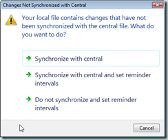
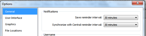
As mentioned earlier, quit out of unneeded applications, set your page file sizes and heed the Autosave warnings:

We know by now that there is technically NO AUTOSAVE in Revit (however perusing the Autodesk app store we did stumble across a promising autosave solution), always save/synchronize when prompted (you will be glad you did) or modify the notifications (every 30 minutes for saving reminder and 60 minutes for synchronizing).

When disaster strikes
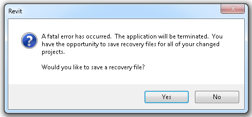
When things go awry, stay calm and Revit on…If you are one of the lucky few that are asked to “Save the recovery file?”, promptly hit “Yes” please. Then go look for a file with the suffix “_Recovery File” which should be in the same location as your original file.
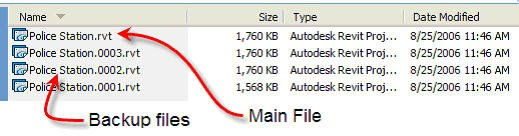
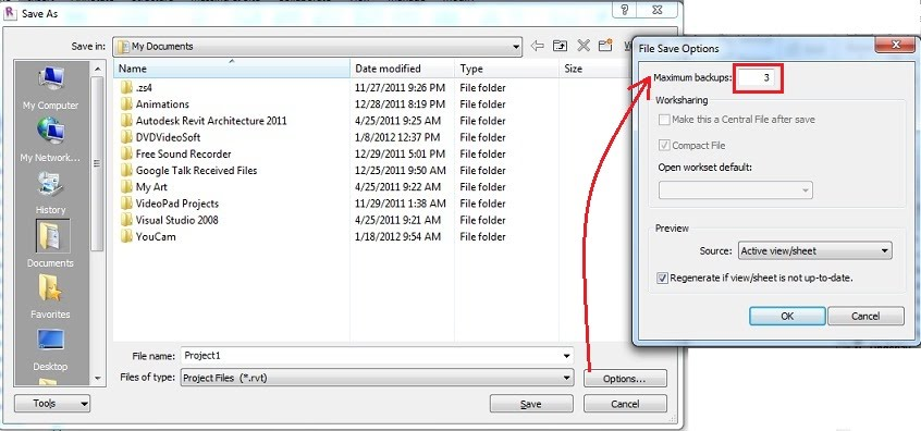
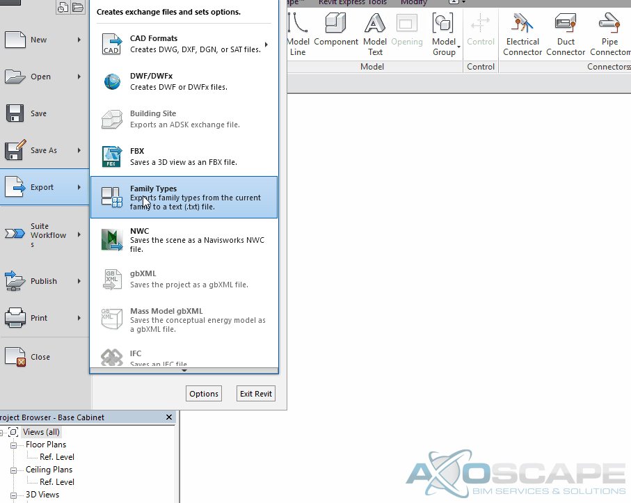
The next best thing is to salvage those saves if you followed our advice earlier, or refer to a backup if your file is corrupt. (FYI the number of backups for non workshared projects can be accessed through the options button located in the bottom right of the Save as dialog).
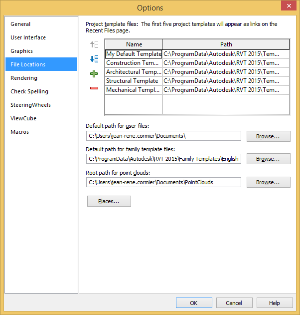
For Workshared or Central files, first, try to access your local file which may be more recent than the central file (especially if you followed our tip earlier regarding save reminders). Local files by default are in “my documents” or check the “default path for user files” in your Revit options:
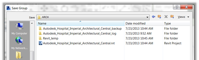
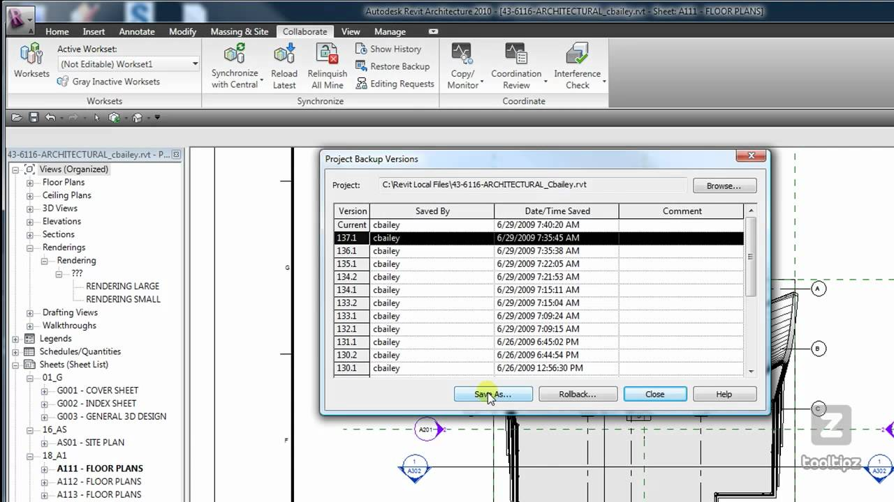
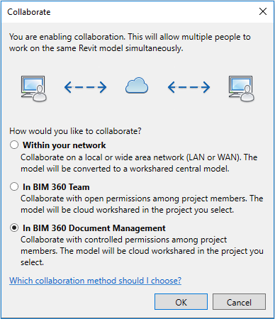
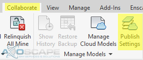
Both the local files and the central files backups are in the “<project name>_backup folder” and can be accessed from the collaborate tab using the “Restore Backup” command however never, I mean never “roll back” your project, unless you want to find a new career, instead, do a Save as and once the backup project has been analyzed, you can just make it the new central:
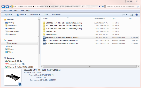
If you are using Collaboration for Revit (a.k.a. C4R), you can try to recover the local file referred to as the “local cache” file in the “collaboration cache folder”:
C:\Users\%username%\AppData\Local\Autodesk\Revit\<Autodesk Revit Version>\CollaborationCache
The filename, however, may be a bit cryptic so just sort by date and start by grabbing the latest one. This technique is especially helpful when you experience internet connectivity issues or when the C4R servers are down.
Journal File Location
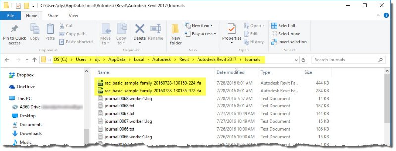
Another place to look for backup files is in the elusive Journal file location. Sometimes, Revit dumps data here, including a partial version of your file/family that may be open at the time. Journal files and their backups may be accessed at the default location:
C:\Users\<user>\Appdata\Local\Autodesk\Revit\Autodesk Revit (VersionYear)\Journals
Or
%LOCALAPPDATA%\Autodesk\Revit\Autodesk Revit (VersionYear)\Journals
What’s in the journal file?
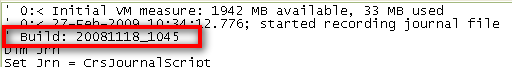
The journal file contains much useful information which is the reason why support personnel may ask for your journal file to make sure you are on the latest build, you have the right hardware and resources and a clue as to what happened before the crash.
Revit Build
Hardware
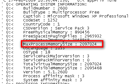
Memory

Errors

Recreate your last session on the fly via journal file.
Many caveats here as you may have better luck getting Congress to pass a law or to agree on a new bill, however it is worth noting that you might be able to get Revit to repeat the last session by dragging the journal file onto your Revit icon. Before you rush-out and proclaim this as the new godsend, follow some of these steps to increase your chances of getting a journal file that will play all the way through (or at least as long as possible).
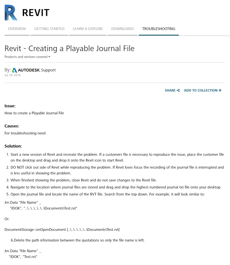
- First, follow the Autodesk article on Revit – Creating a Playable Journal File included here for your reference.
- Second, as finicky as the journal file is, make sure to:
- not switch tasks while in Revit and
- avoid moving windows around or
- resizing windows within a session.
- The fewer error pop-ups you have, the more success you may have at journal file playback.
- Use keyboard shortcuts whenever possible (not only is this more efficient, but will rely less on mouse pointer positions and clicks)
Nothing ruins your day faster than crashing and losing a bunch of work. We hope you find some value in the tips and techniques to help ease the pain, if not, just an ample reminder for all the Revit folks from time to time is sufficient. Got a disaster recovery method that we didn’t mention? We would like to hear (and so does the rest of the world), so feel free to share!
Shoutouts:
(Brian Mackey) for his awesome journal file class and insights at http://www.rtcevents.com/bilt/na18/
for the multi-part journal file story on http://revitclinic.typepad.com/my_weblog/2009/03/a-journal-file-story-part-1.html
Autodesk support and knowledge base https://knowledge.autodesk.com/support/revit-products/troubleshooting/caas/sfdcarticles/sfdcarticles/Revit-Creating-a-Playable-Journal-File.html
and the numerous folks who posted questions regarding Revit’s file recovery process.


