As a Revit user when starting off a project, the Project Coordinator will distribute some files to link into your model as a starting point. They will typically send out dwg, RVT, and/ or NWD files. There is always a project that will throw a curveball to the project. One of the biggest curveballs anyone can get hit with is working with a new file type. In this case, I will be discussing some differences from working with prototypical file types versus something like an IFC and a NWD.
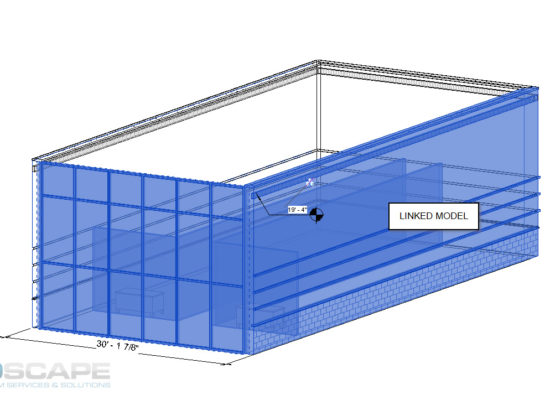
In most cases, an RVT file would be the ideal format to work with since Revit understands it completely. Dimensions strings and elevation tags are a few of the annotation features a Revit user will be able to use on a linked RVT file.
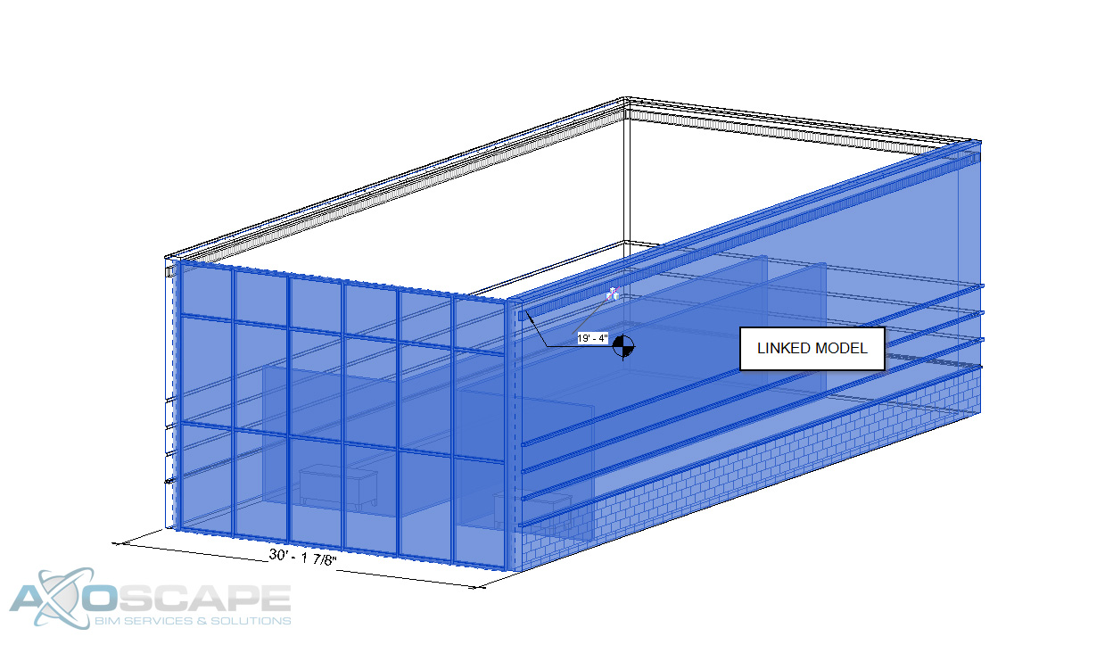
Another great feature the user has when linking another Revit model is the align command. This is very crucial when lining things up with another model. Reason being is the fact that the user is able to select the component. Having this ability helps to review some of the parameters from this file.
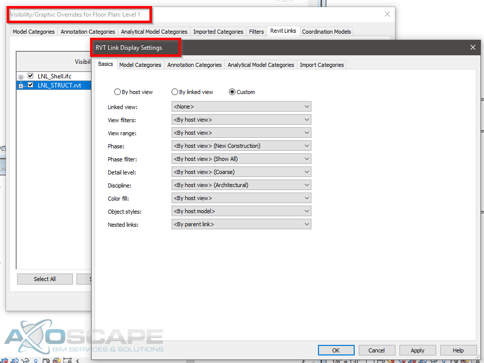
The best part about linking another Revit file into a project is having the ability to schedule out everything from the project. Since it only contains Revit components the schedules will be 100% smart. Visibility graphics can override components within Revit, which means the linked RVT file will be affected as well. BUT it also has its own visibility settings in case the user doesn’t want to change a few components of the project.
DWG’s are the next typical file type to link onto a project. This file type limits the user on some of the things that can be achieved. For instance, the ability to use the elevation tag. However, by creating a dimension string, the user will still be able to find out the height of something.
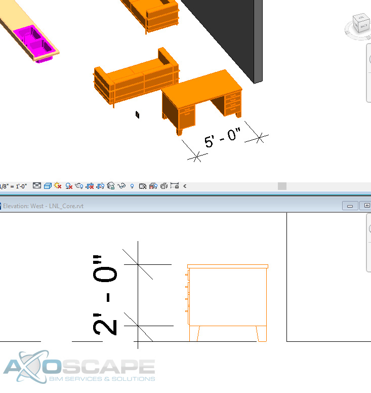
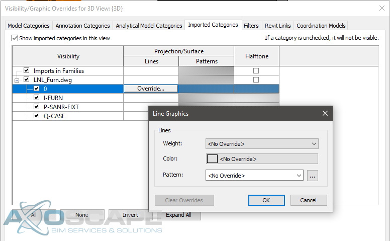
Aligning items to faces of a DWG is a plus when it comes to lining things up nicely especially when it is at an angle. The only thing that can be overridden on a DWG is the line weight, color, and the line type.
If a schedule is created to read all the furniture equipment in a project, it will be blank since Revit does not recognize DWG elements. However, there is the ability to insert blank rows and insert all the information for the DWG elements with the caveat of manual updates.
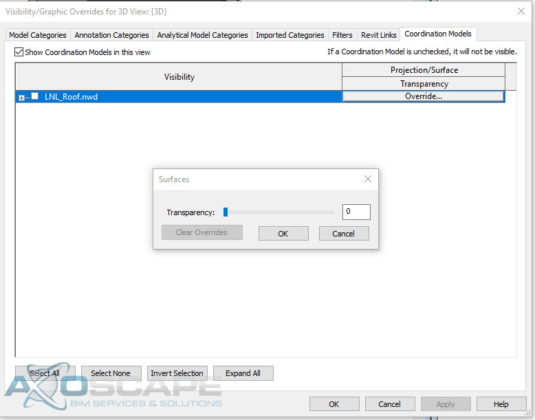
NWD’s limits the user on what they can and can’t do. From working with NWD’s, the idea behind it was having the ability to coordinate within Revit. With an NWD model, the user is not able to select any of the elements or even change the color, line type, nor the line style. The only thing that can be overridden is the transparency level.
Now IFCs can be tricky to work with. Since IFC’s are typically produced from a sketchup model, all the elements are faces and not solids. Which means if the person that created the IFC model accidentally shifts a vertice on a face the whole face might not display correctly in Revit. This will cause problems when trying to align elements.
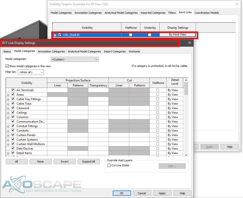
One good thing about IFC models is having the ability to override components similar to how the user would if they were working with another Revit model.
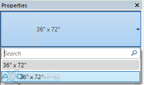
It is able to recognize all the different components. With IFC’s the user is able to copy and paste elements, BUT I wouldn’t recommend it since it will only load the copied elements from the IFC model. Here is an example of copying a window from an IFC model vs the window library in a project.
IFC Library
Revit Library

Another thing about copying the elements from an IFC model into the Revit file is if a schedule was created to read all the windows, the copied IFC windows will come out blank due to no size parameters.
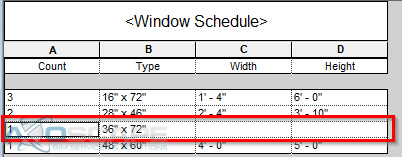
If the IFC file is on Revit 2018, it will allow you to input the size in the window but it’s not 100% accurate due to the window not being a RFA (Revit family). Which means any size can be placed on the window but it will not reflect the physical model inside the file.
In conclusion, using a Revit file or an IFC model can be some of the best references. Since the IFC files act similar to how a Revit file is with the exception of a few parameters. DWG is the next best thing to work with, and if there’s any coordination involve with any MEP components. Or if the project is fairly large then I would use a NWD model to minimize the file size. Especially if it’s only to reference on the location of elements.