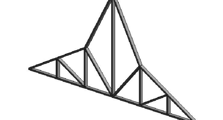
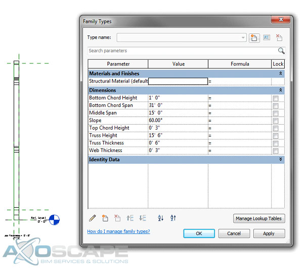
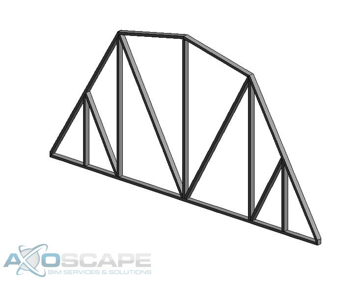
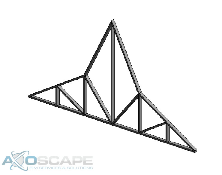
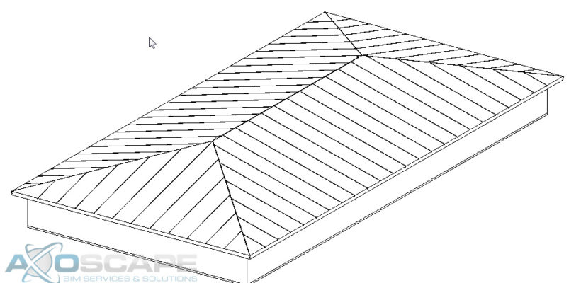
When creating this type of family you can make both a Polynesian and a Gambrel roof truss with this one model. It can be tricky to create this family, but in the end, it could save you time once this family is finished.
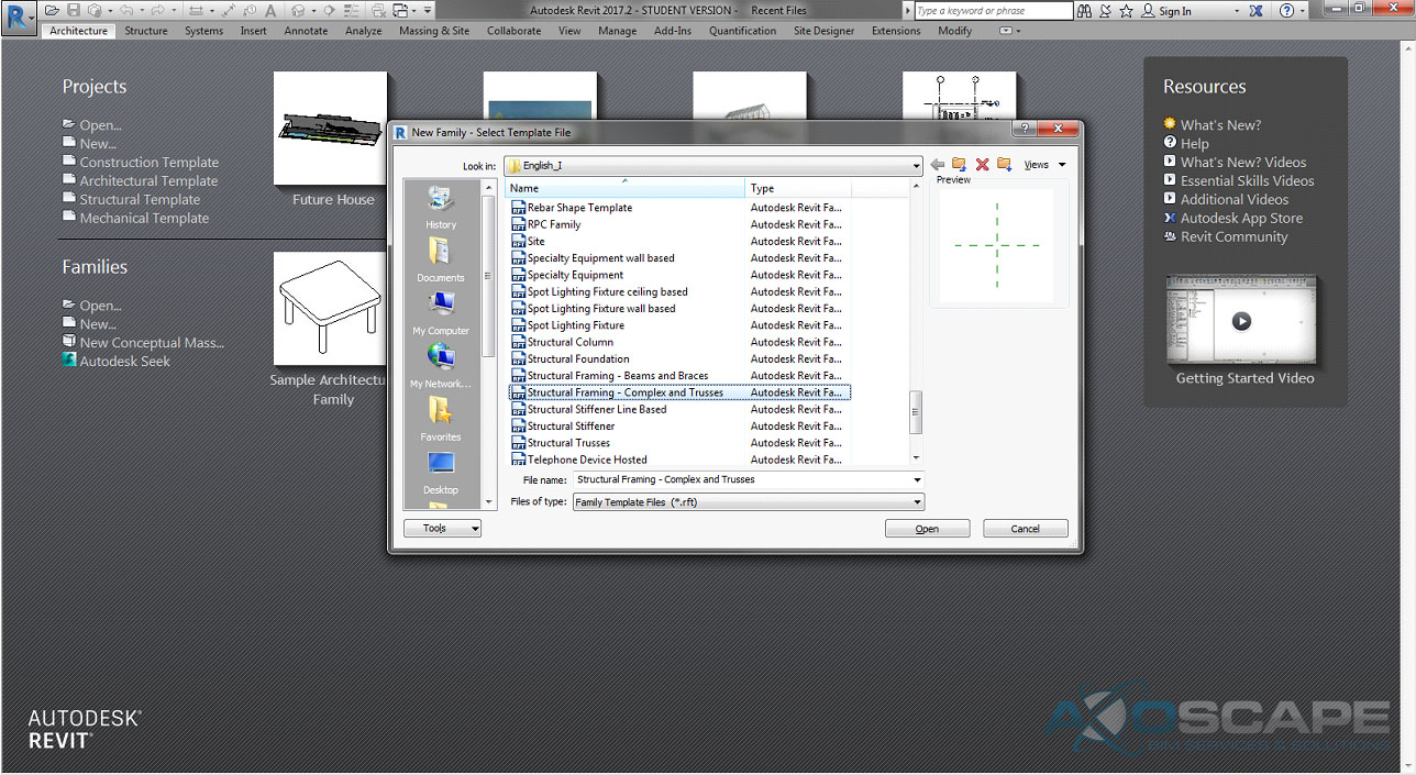
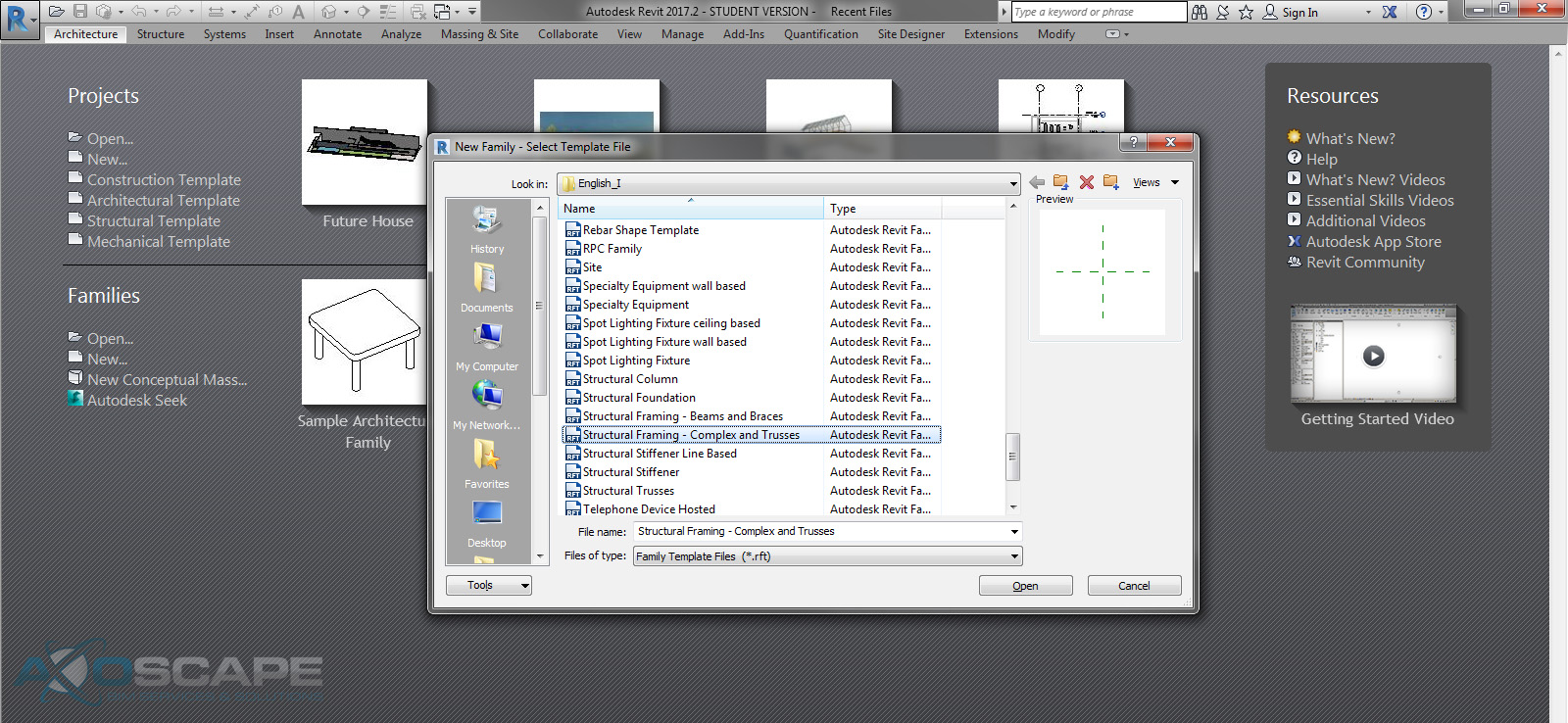
⦁ Open up Revit and create a new Structural Framing – Complex and Trusses
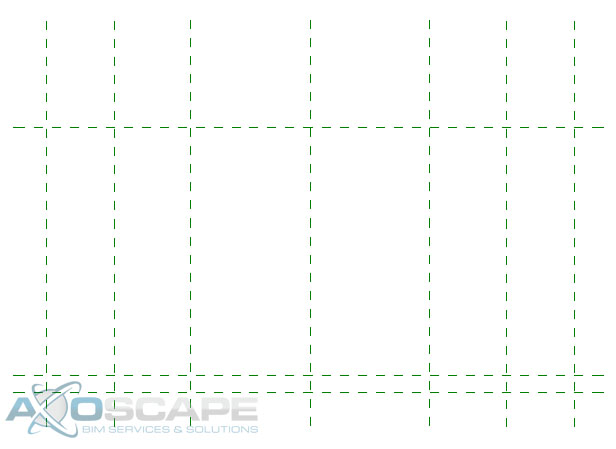
⦁ Open up the front elevation and hide the level in visual graphic (VG).
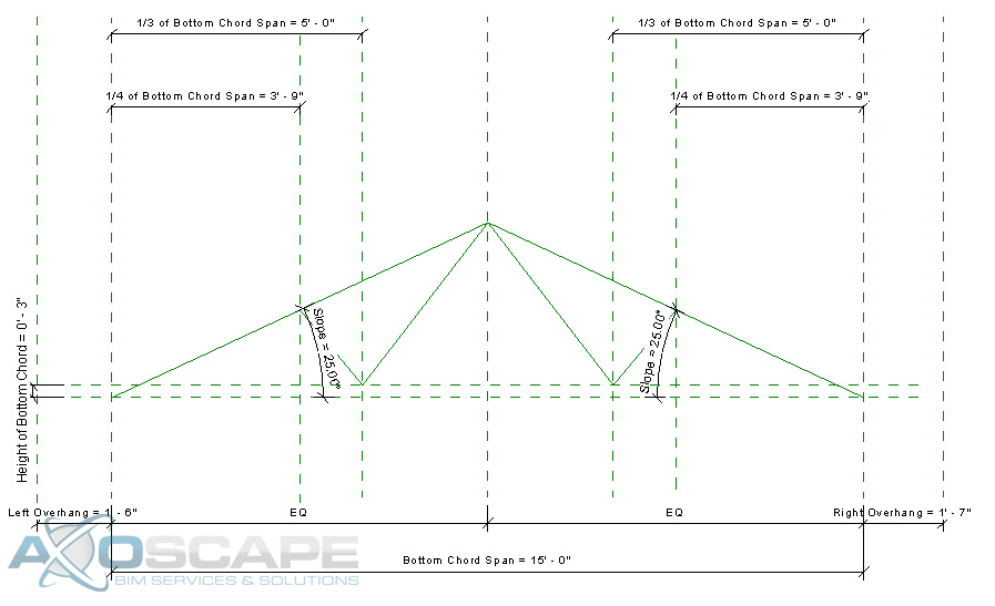
⦁ Create three vertical Reference plans on each side of the center axis.
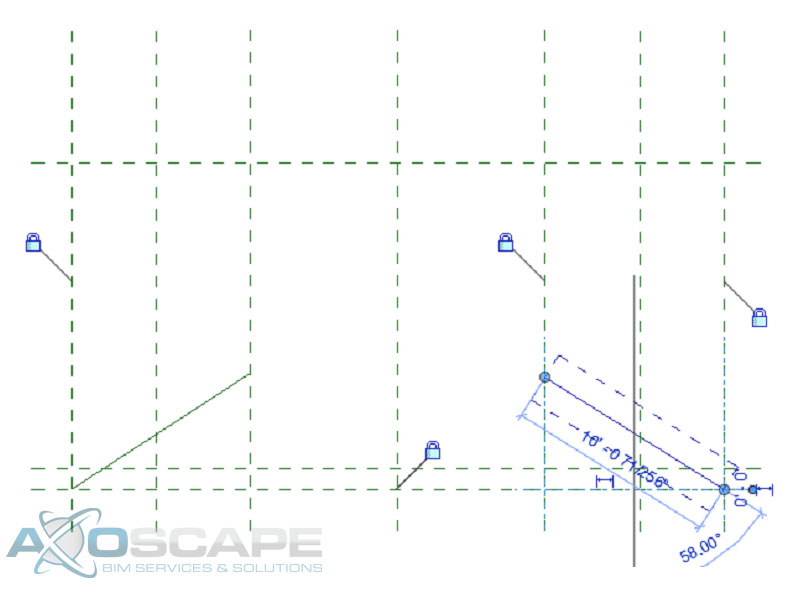
⦁ Create two diagonal reference lines to create the slope of the top chord of the truss.
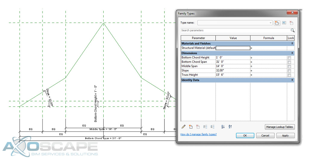
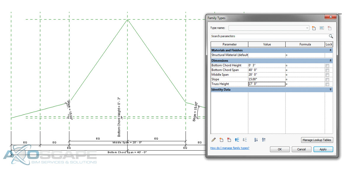
⦁ Add a dimension parameter for the bottom chord span and lock the parameter then equal space between the overhangs with a dimension.
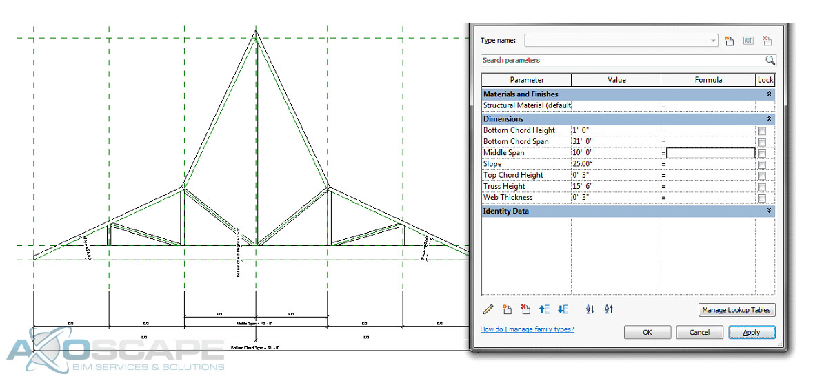
⦁ Add a dimension parameter for the middle span and lock it, then test to see if reference planes change.
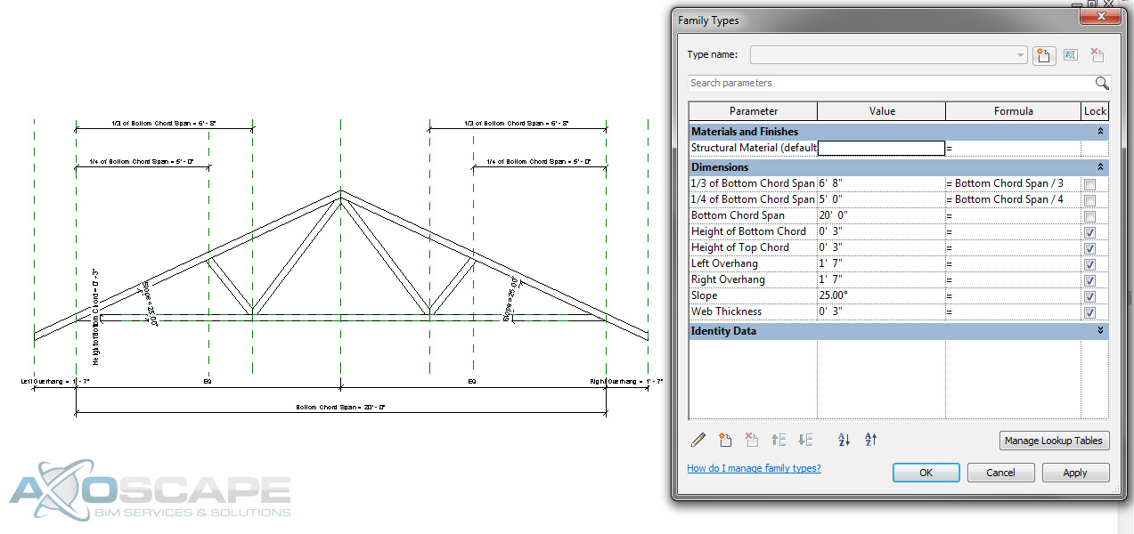
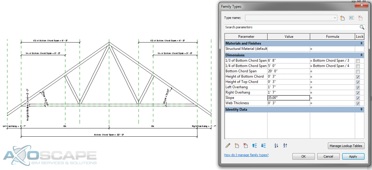
⦁ Add an angle dimension parameter to each slope and lock it.
⦁ Add a reference plan for the top of the bottom chord and add a dimension parameter for the height of the bottom chord.
⦁ Add a reference plane at the top of the truss and add a dimension parameter for the truss height.
⦁ Test to make sure things are working correctly.
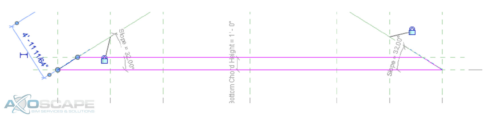
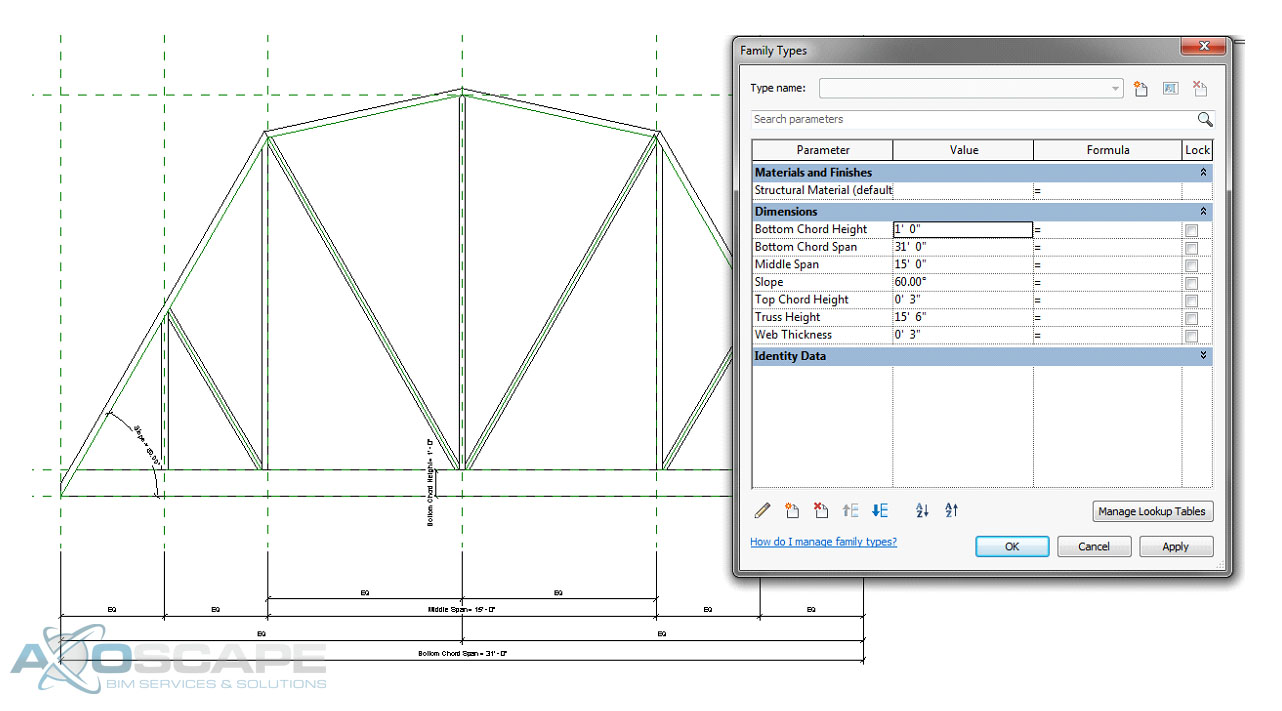
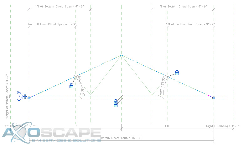
⦁ Using the extrusion tool create the bottom chord span by using the pick lines and trimming to get the shape, also lock the lines to the reference planes.
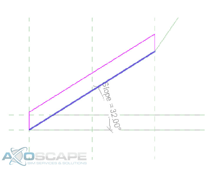
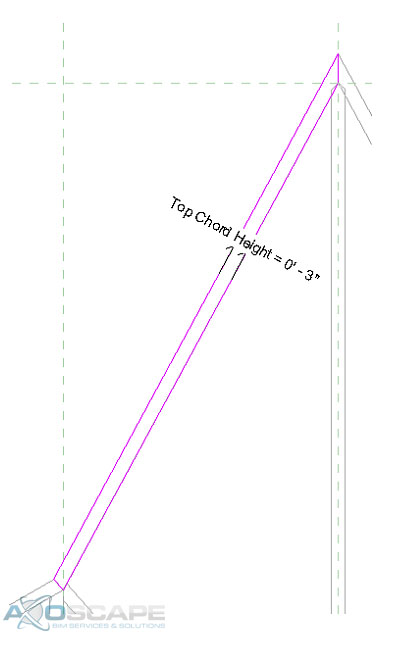
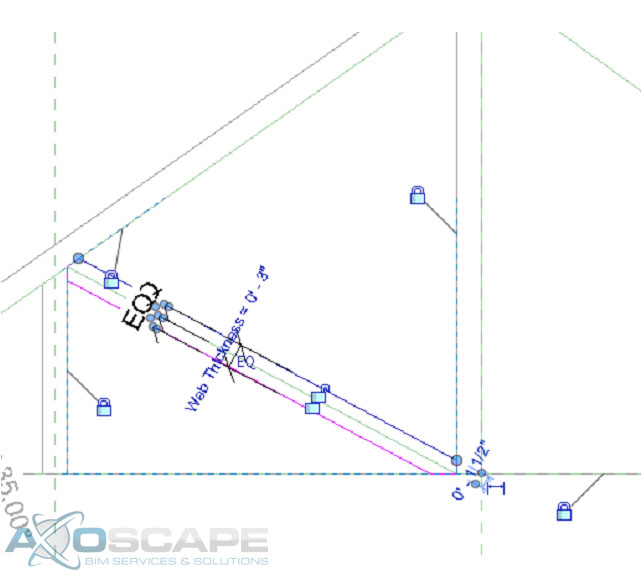
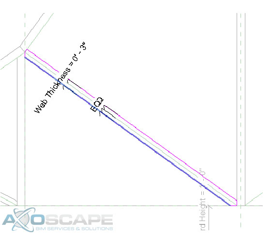
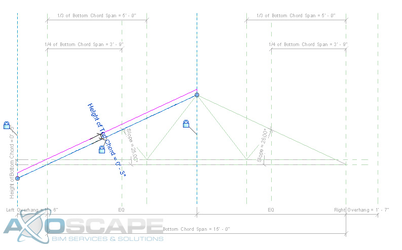
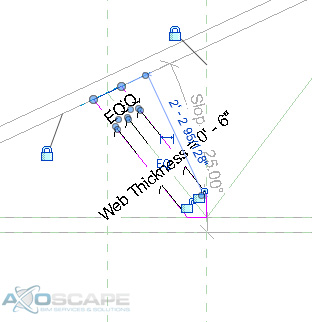
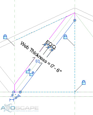
⦁ Do the same thing to create the top chords for each side, also add a dimension to control the height of the top chord and make sure you lock it to the reference line. ⦁ Extrude the webs on each side by using the two vertical reference planes on each side, also add a dimension parameter for the web thickness.⦁ Use the extrude tool make middle web member the same way.⦁ Test to make sure things are working correctly.
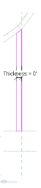
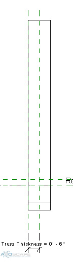
⦁ Add reference lines for the webs to each side and lock it to the top and bottom chords. Then test for function.⦁ Use the extrusion tool to create the web of the truss in two separate pieces. Center the web around the reference line and dimension the width of the web.⦁ Test to make sure everything works accordingly. ⦁ Open up the left elevation and create a reference plane for the thickness of the truss and align extrusions to the reference plane. Then test to make sure everything works like its suppose to.
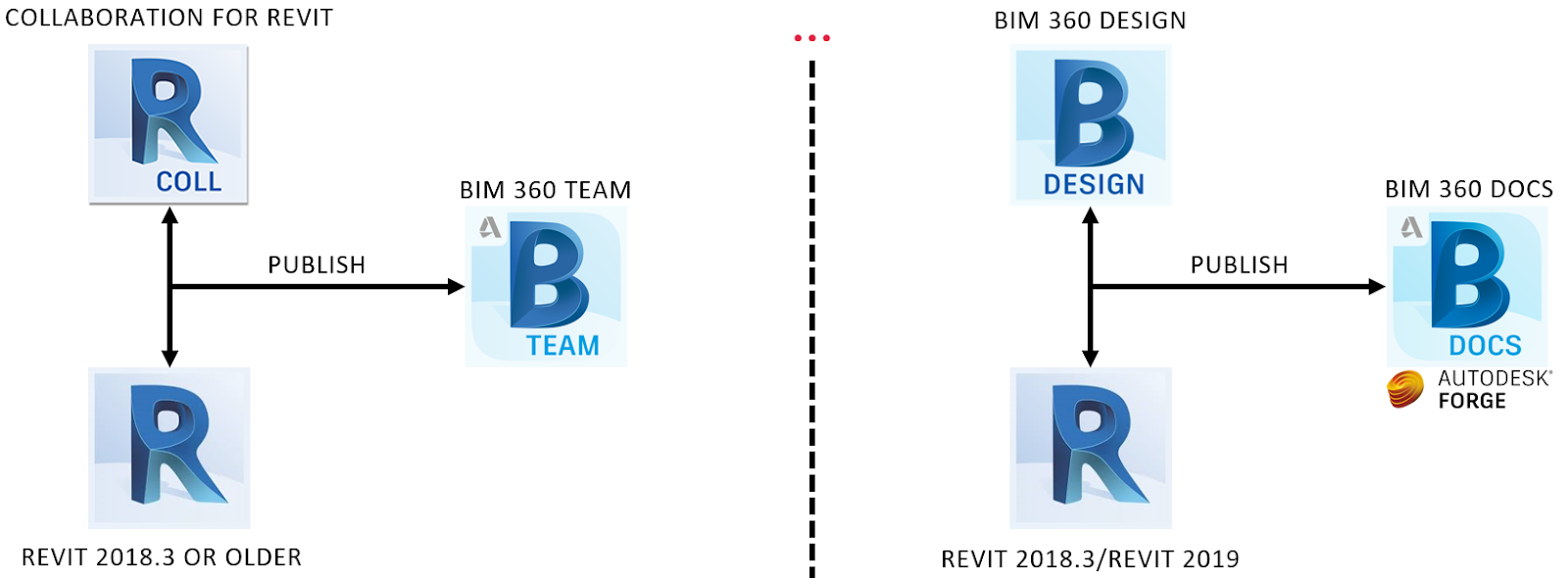
On April 9th, Autodesk released the next generation of cloud worksharing aiming to replace what we currently know as Collaboration for Revit (C4R) and rebranding it as BIM 360 Design. On the technical side, Autodesk argues their services change in order to provide a better experience on Forge based platforms, however, there are some licensing differences as well. Without getting too much into the financials, this tutorial series intends to review and show new workflows using this next generation of tools that we have inherited. This new BIM 360 Docs environment is definitely more powerful, but it will require more set up time for the permission portion until your team finds the right way to share data within your projects.
“Our ability to adapt is amazing. Our ability to change isn’t quite as spectacular. “ —Lisa Lutz
The facts presented here are based on the limited time we had for testing since the release date. Please, let me know if you find any discrepancies. Let’s start!
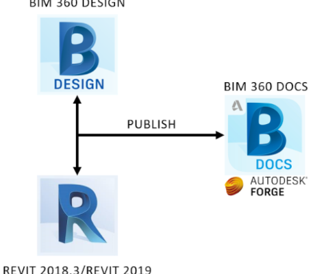
Notice Revit 2018.3 is the only version that works with the old and new cloud worksharing platform (C4R and BIM 360 Design). The user still has to hit the publish button in order to reflect the latest Revit model changes to BIM 360 Docs (Also, can be done from Docs). After diving into Revit 2019, there is no going back to C4R. Autodesk will continue to provide support for BIM 360 Team. However, Autodesk will do its best to convince your team to use BIM 360 Docs for your next project. With that being said, no migration tool is going to be provided to transfer projects from BIM 360 Team to BIM 360 Docs.
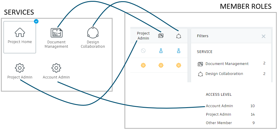
An exciting feature of the new platform are permissions and access levels for company hubs and project members. In addition to this, in the Design Collaboration module, Project Admins can create teams (Services > Design Collaboration) to manage cloud models, allowing another level of control while also avoiding interference with other teams. For this reason, the workflows presented on this tutorial address not only how to get started with a cloud project, but also how to properly add users using multiple methods to filter access levels while facilitating the data and communication flow.
The image below maps the services activated in a project and members’ access/roles assigned.
The Workflow on Video
Disclaimer: If you hear me saying “BIM 360 Ducks”, I mean “BIM 360 Docs” 🙂
How can I add users/members to my BIM 360 Docs Project?
Add a project Team for Design Collaboration (As Project Admin)
Problem: I created a project, but I cannot see its project folder though Revit > Open
Solution: Users will not be able to see the project folder in Revit until the first Revit model has collaborated to the cloud (BIM 360 Document Management). See video below.
Collaborate the first model to BIM 360 Document Manager (As Project Admin)
How can I collaborate the first Revit Model and assign members to a Design Collaboration Team?
Problem: I created a Design Collaboration Team, how can I add members to it?
Solution: (Project Admin > Services > Design Collaboration) Click on the checkbox of the Team you want. Next, click on Manage team members. Finally, Add them and assign permissions. See video below.
Collaborate a model to BIM 360 Document Manager (Access Level: View-Edit)
A user is assigned to a Team to collaborate a model to the cloud.
Problem: A Design Collaboration Team member collaborated a revit model, but nothing has been shared from other teams so, this user can bring context to his/her model
Solution: In order to have access to other Team’s models, they have to create a Package using the Design Collaboration module and share it with other Teams. See video below.
Meet the Design Collaboration Module and Create a package
Problem: A Design Collaboration Team member can open and edit Revit files from its own Design Collaboration Team, but I cannot share packages with other Design Collaboration Teams
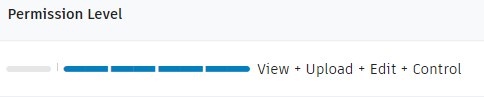
Solution: This user probably does not have the required permission level. Make sure the permission level (Project Admin > Services > Design Collaboration) is set to View-Edit-Share
Adjusting Permission Levels and Sharing Packages
Reusing Design Collaboration Packages
The “Reuse” command uses the document version of the package we plan to reuse.
The create “New Package” command uses the last version that has been published from Revit or Updated to Latest from Design Collaboration
Revit: Publish Latest vs. BIM 360 Design: Update to Latest
Consumed Packages
Decide what shared Revit files link to your Revit Model using the “Consume” command
Shared vs Consumed Packages
BIM 360 Docs Permissions
Notice that this workflow also works with Automatically created folders (from Design Collaboration Teams)
Also, the permission level showed below provides almost Admin level power just for that folder that is assigned to.
Big thanks to the person from Autodesk that put the document under references together and to Ignacio Rodriguez and Tony Trinh who helped me with content and video editing. Finally, shoutout to Katie Watton, who is creating more in-depth and relevant learning content about this topic for the CADLearning team.
When creating rafter tails with a beam system, it can be difficult. Also, if you need to have a custom rafter tail end, you will need to modify both ends of the beam to your desired design.
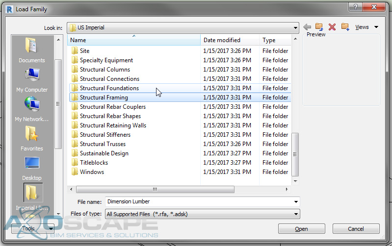
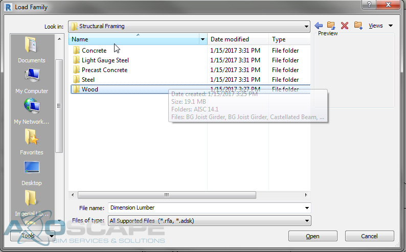
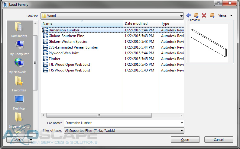
Select the structure tab and select the beam tool. Then load the desired structural framing family you would like to use.
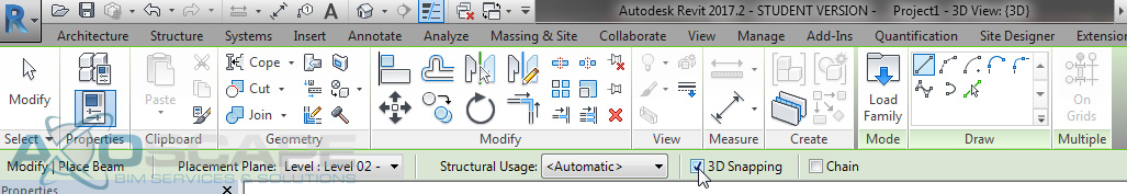
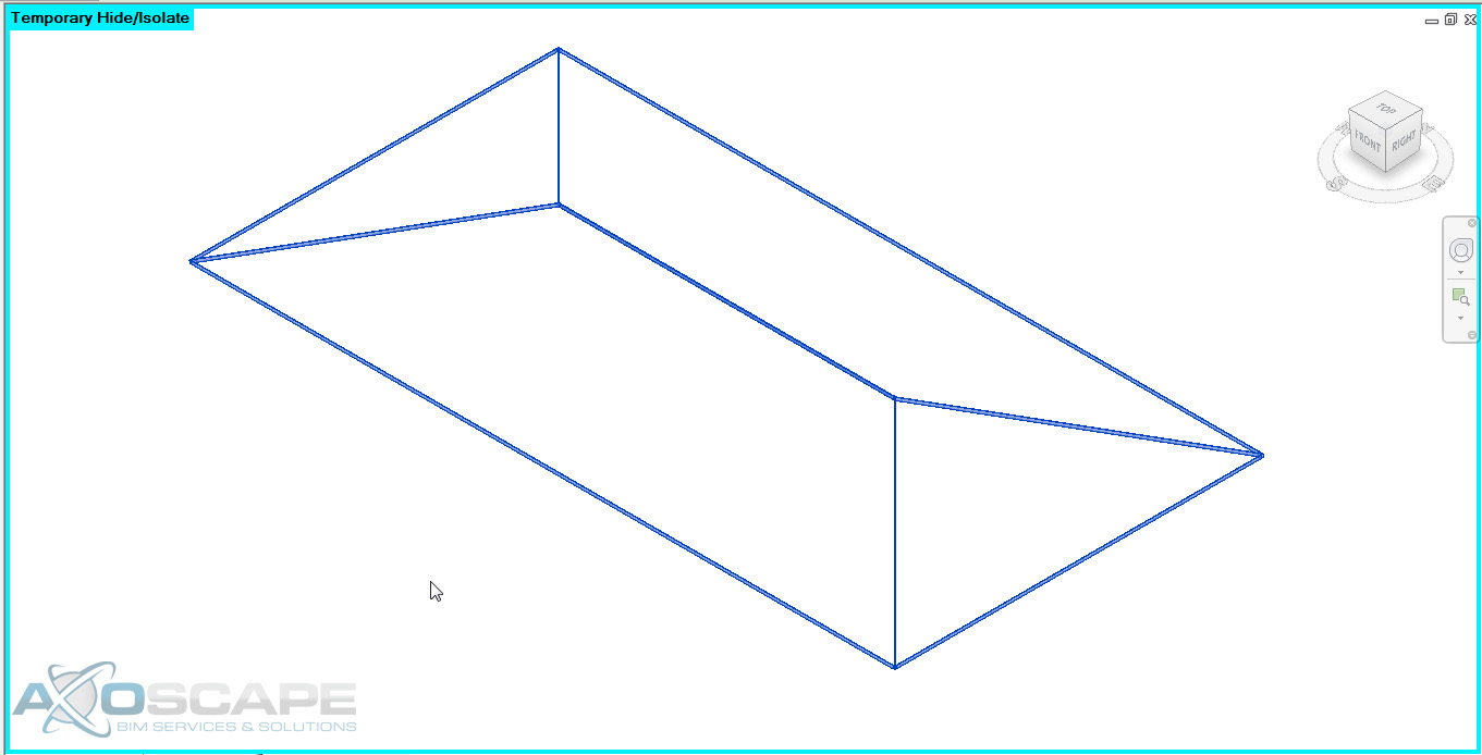
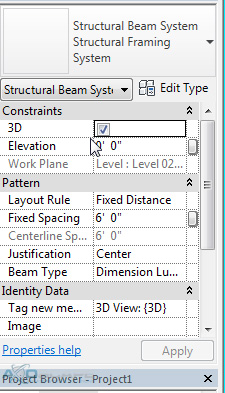
Now, after selecting your desired beam, switch to the 3D view and before selecting lines to create the beam make sure the “3D Snapping” box is checked.
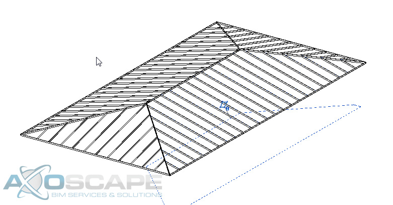
Use the “pick lines” select the ridge, hips, valleys, and edges of the roof.
Select all of the beams you just placed and isolate the beams using the “isolate element”
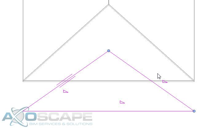
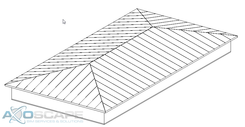
Go back to the structure tab and select the beam system tool. Make sure the 3D box id checked before selecting the beams. Then using the “pick supports” and select one section of the roof beams.
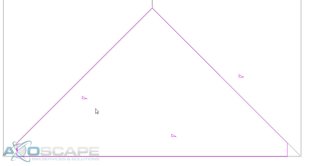
At the bottom corners, you will need to make two straight line so that the rafters are perpendicular to the roof edge. Select one as the “beam direction”
Do the exact same thing to the other sides of the roof to continue to have the rafter tail on all sides.
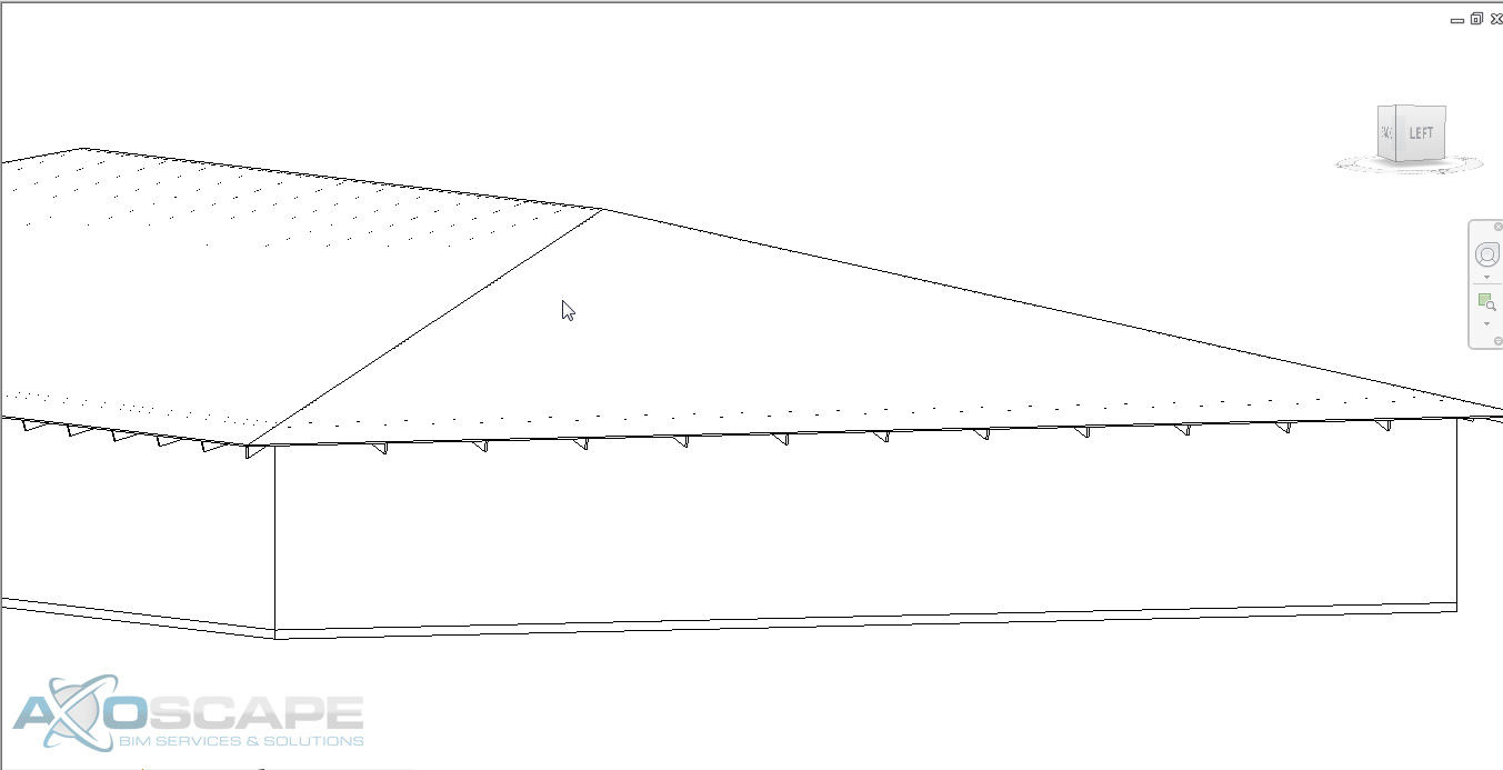
Un-isolate the roof rafters and beams, and you can see the rafters and beams through the roof. But before we deal with that create a design option called “fascia” so that you can hide the beam that is at the edge of the roof.
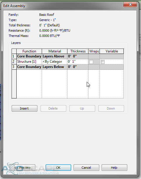
To hide the rafters and beams you will need to modify the roof and make sure that the roof sits on to of the rafters and beams. Make the roof 1” thick (or what the thickness of the desired roof system). And then offset the roof so that it sits on top of the rafters.
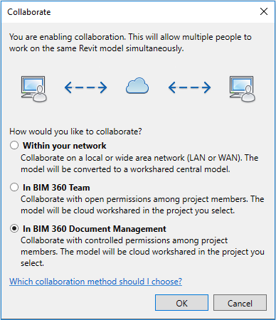
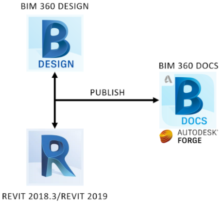
Autodesk released Revit 2018.3 and BIM 360 Design (Rebranded Collaboration for Revit) merging Revit and BIM 360 Docs.
Autodesk is moving away from BIM 360 Team into a Forge based environment. Your current projects will be still hosted in the Team environment for Revit 2018.3 and older versions. Check out the new interface!
Notice the 3rd option to collaborate files “In BIM 360 Document Management” which will basically sync your Revit project in BIM 360 Design and it will be reflected in BIM 360 Docs.
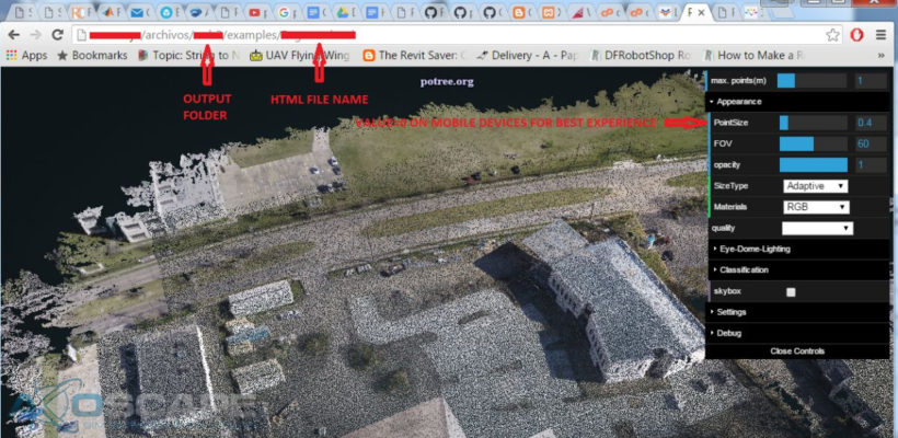
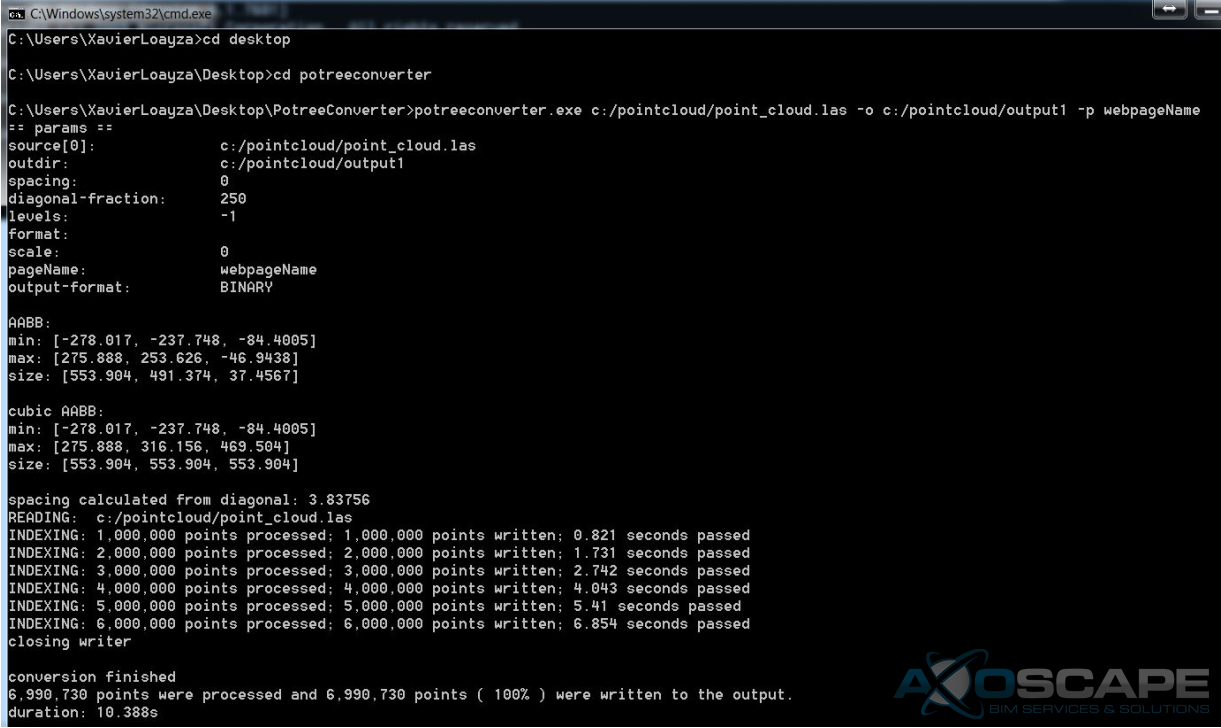
This short tutorial shows how to share 3D point clouds using potree.org, an open source web tool. Potree Converterconverts .las, .laz, binary ply, xyz or ptx files to a format file readable for web browsers.
Steps:
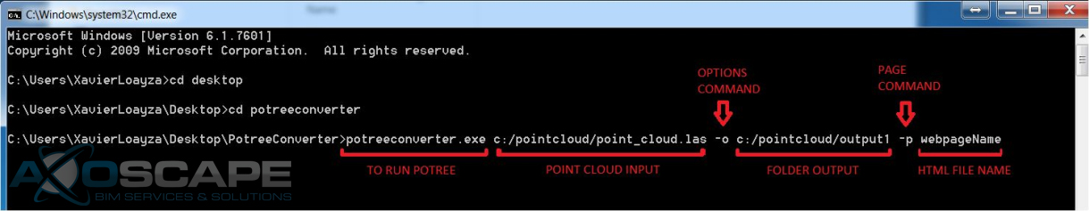
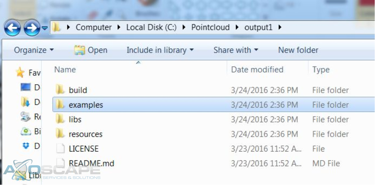
DownloadPotree Converterand extract the .zip file anywhere ie.
C:\Users\<USER>\Desktop\PotreeConverter\
Open cmd to run PotreeConverter.exe
You are going to see this when it finishes processing
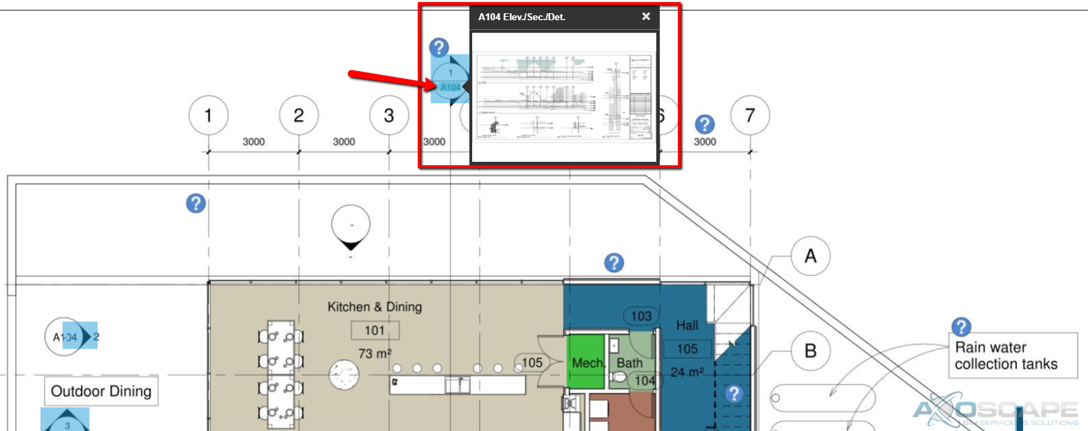
In this tutorial, we want to explore how to upload Sheets to BIM 360 Docs and extract some data from them by recognizing text within the title block. Extracting data from sheets might help to link our construction documents better. As we know, we could even get that data without printing by just plugging some Dynamo nodes getting parameters of the sheets. However, the intention of this article (and hopefully a series of them) is to explore some OCR tools and computer vision for object detection. We will see how that goes…
In the meantime, we will use BIM 360 Docs and try to get the best of it. The following animation shows the process of uploading a set of documents to Docs.
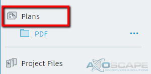
Upload pdf to a folder inside the “Plans” section because this section breaks down PDF, RVT, and DWG files into views and sheets. On the other hand, the “Project Files” section can take any type of files like BIM 360 Team, but it will not do OCR on sheets. It will serve as a storage hub which includes viewers.
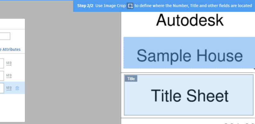
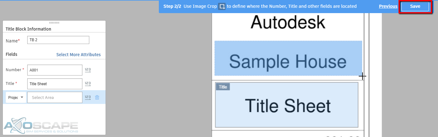
Extract information by using a Layout Template. If this a new set of sheets, the user will have to select the title block area where the information is. Also, the user will have to specifically select the area the sheet number and sheet name is in the title block. The tool is assuming the set of sheets have the same size and the title block is in the same position.
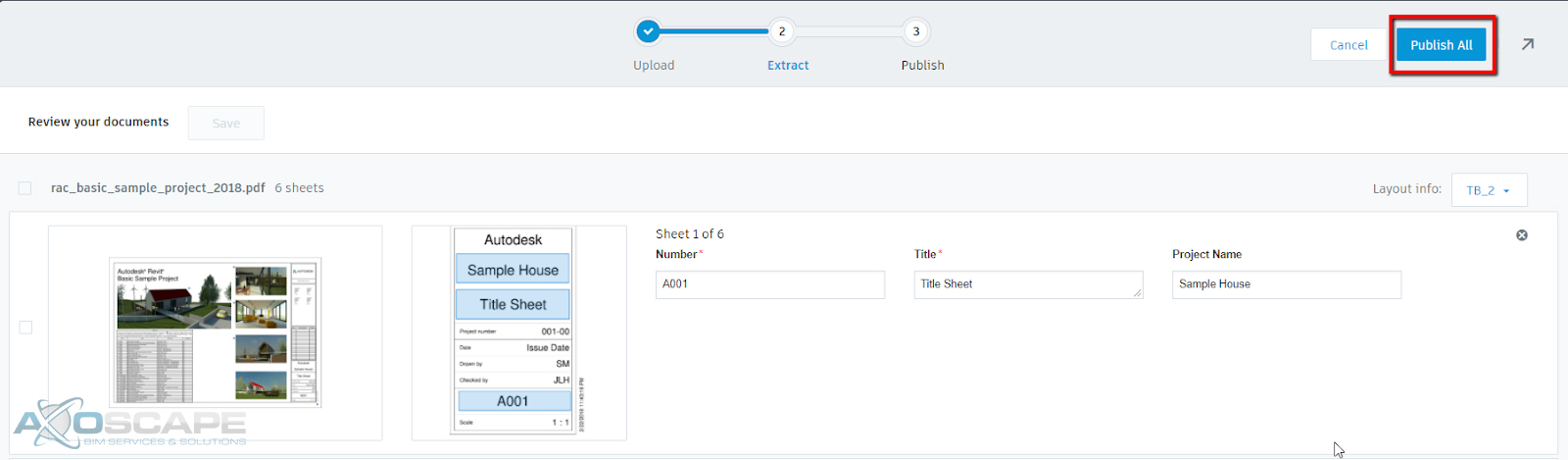
Publish the sheets after reviewing the documents and the data extracted from them.
It will take a couple of minutes to process in the background, but you will also receive an email while is ready to view. After this process, the attributes extracted will show up as columns and also, any view reference will be available as hyperlinks that allow jumping from sheet to sheet as long as they are under the same folder.
Add more attributes to your sheets!!! It is possible to select more fields by adding more attributes. This could serve to sort your sheets by a custom attribute aside from sheet name and number, but also to extract more important data. See the animation below.
When creating a roof truss, it is tempting to use the one that Revit has supplied. The problem with that is, that truss does not include the overhang that is needed to make a roof truss. Instead, it is better to create a family in which you can manipulate to meet the needs of the project.
Open up Revit and create a new Structural Framing – Complex and Trusses.
Open up the front elevation and hide the level in visual graphic (VG).
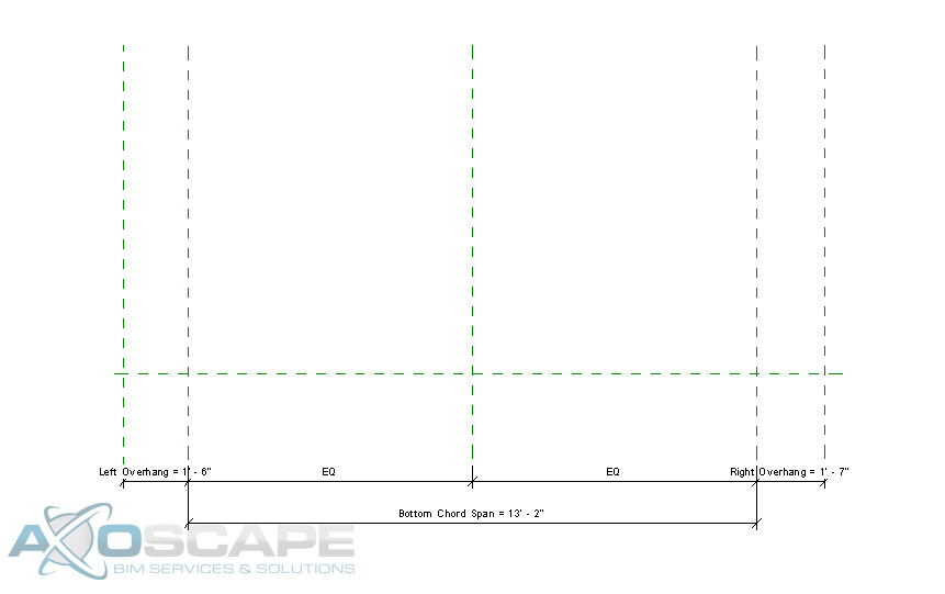
Create two vertical Reference plans on each side of the center axis.
Add a dimension parameter for the overhangs (left and right) and lock the parameter then equal space between the overhangs with a dimension.
Add a dimension parameter for the bottom chord span and lock it, then test to see if reference planes change.
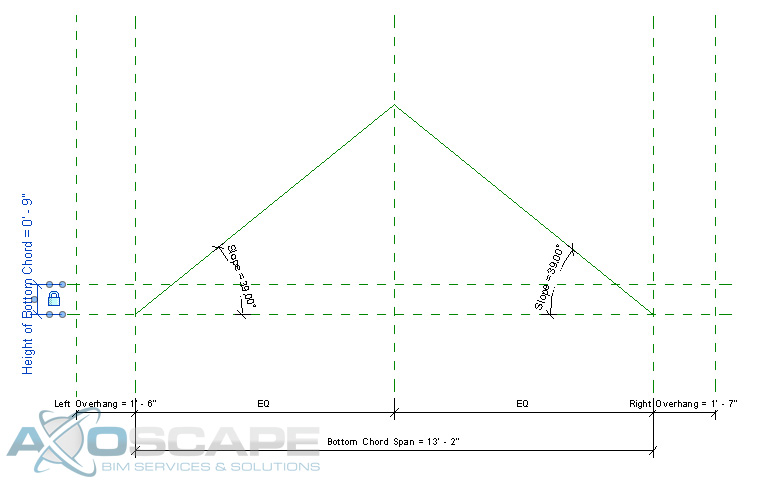
Using a reference line on each side create the slope of the truss and lock them to the reference planes (make sure to uncheck the chain box and align to the center plane and lock).
Then add an angle dimension parameter to each slope and lock it.
Add a reference plan for the top of the bottom chord and add a dimension parameter for the height of the bottom chord.
Test to make sure things are working correctly.
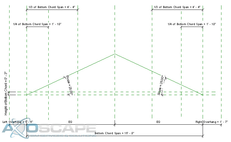
Next, create the web by using two reference planes on each side.
Then create parameters for the location of the web intersections.
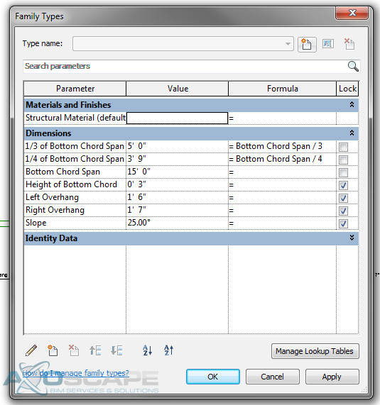
Then enter formulas for each parameter to control the web placement.
¼ of Bottom Chord – Bottom Chord Span / 4
of bottom Chord – Bottom Chord Span / 3
Test to make sure things are working correctly.
Add reference lines for the webs to each side and lock it to the top and bottom chords. Then test for function.
Now using the extrusion tool create the bottom chord span by using the pick lines and trimming to get the shape, also lock the lines to the reference planes.
Now do the same thing to create the top chord for each side, also add a dimension to control the height of the top chord.
Now using the extrusion tool to create the web of the truss in two separate pieces. Center the web around the reference line and dimension the width of the web.
Test to make sure everything works accordingly.
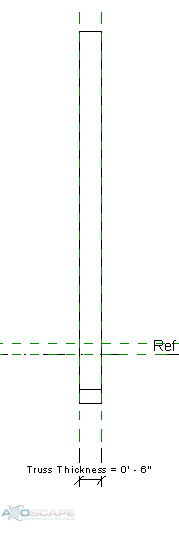
Now open up the left elevation and create a reference plane for the thickness of the truss and align extrusions to the reference plane. Then test to make sure it works.
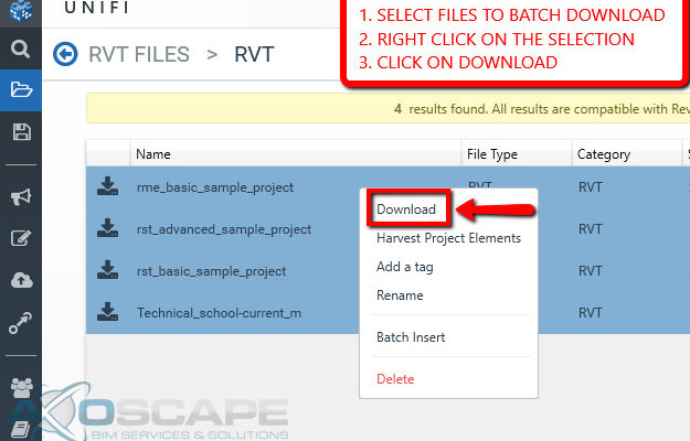
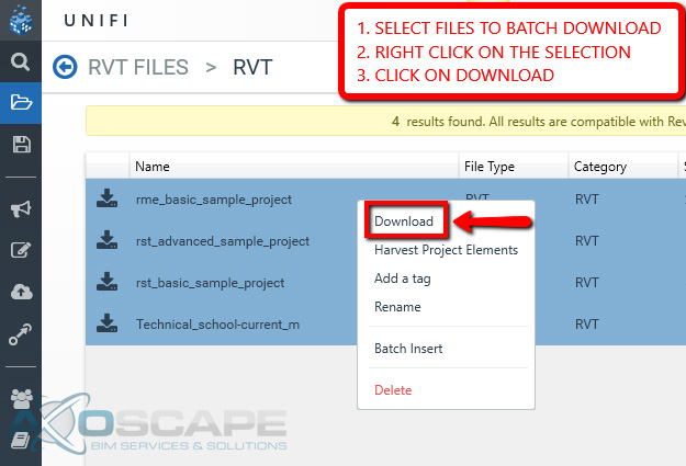
UNIFI just improved the tool for batch downloading RVT models, today! In addition to the steps to batch download, we will use “Bulk Rename Utility” to move the RVT files from the UNIFI download directory to a different folder.
Let’s start!
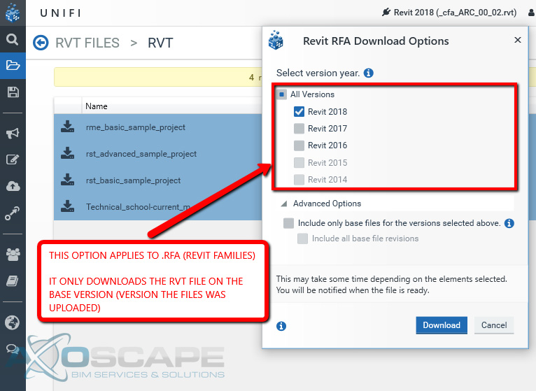
The next window works for .rfa files. It will not download the files in the version selected, but the base version.
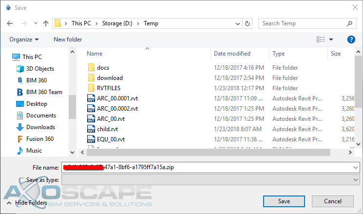
Save the zip files to the desired directory.
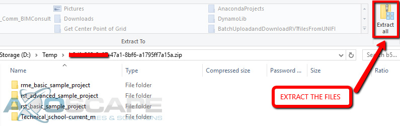
Extract the zip files.
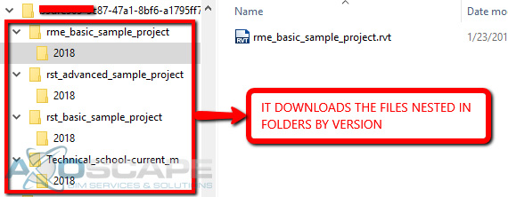
The image below shows UNIFI’s folder structure for Batch Downloading files.
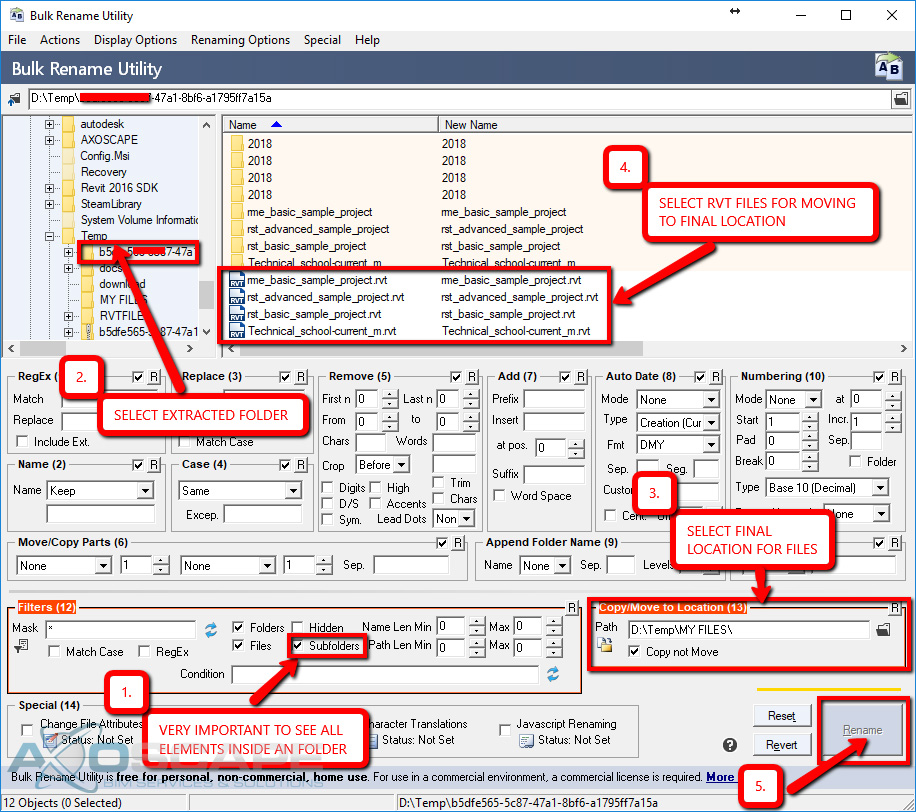
Now, let’s use Bulk Rename Utility dig in the previous directory and move only the RVT files to a new location.
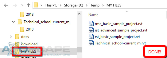
Finally, we are done!
Note: UNIFI is working on giving us more options to download our data!
 ⦁ Extrude the webs on each side by using the two vertical reference planes on each side, also add a dimension parameter for the web thickness.
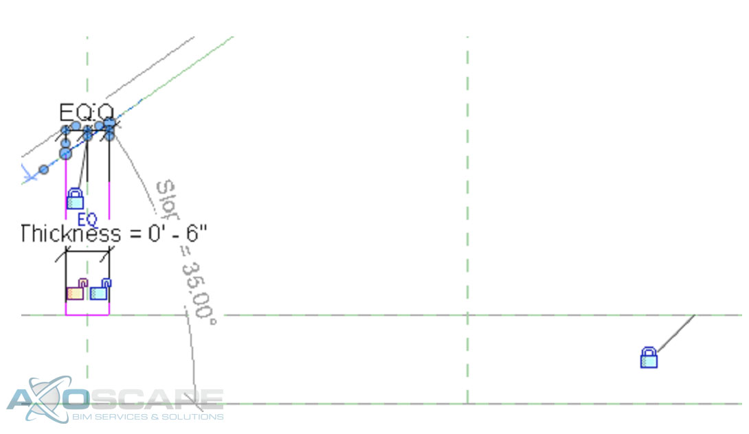
 ⦁ Use the extrude tool make middle web member the same way.
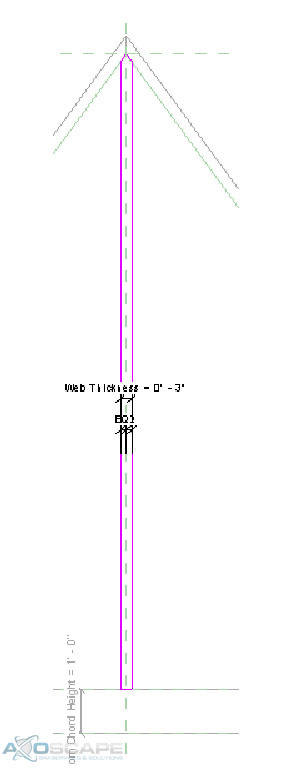 ⦁ Test to make sure things are working correctly.
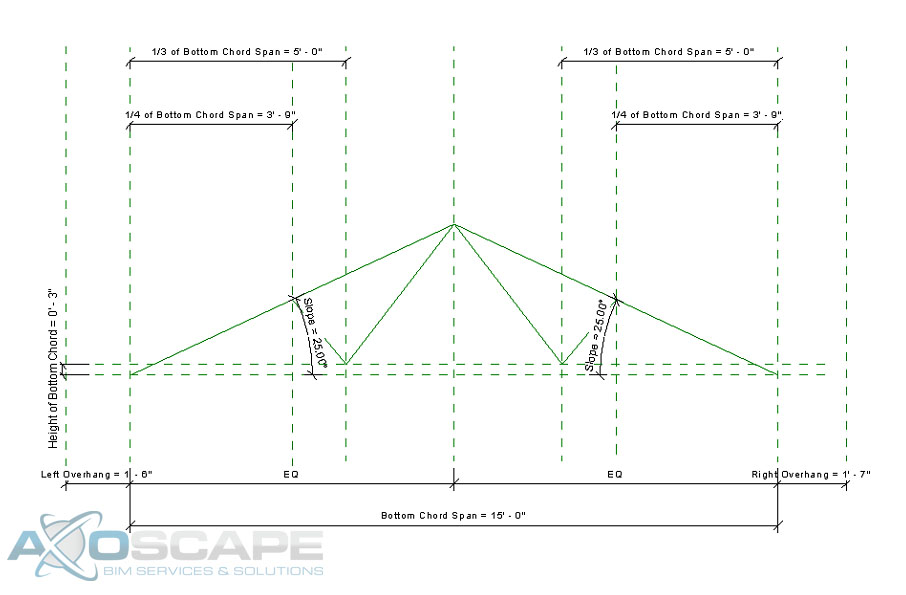 ⦁ Use the extrusion tool to create the web of the truss in two separate pieces. Center the web around the reference line and dimension the width of the web.
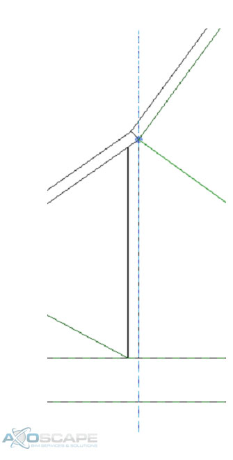
 ⦁ Test to make sure everything works accordingly.
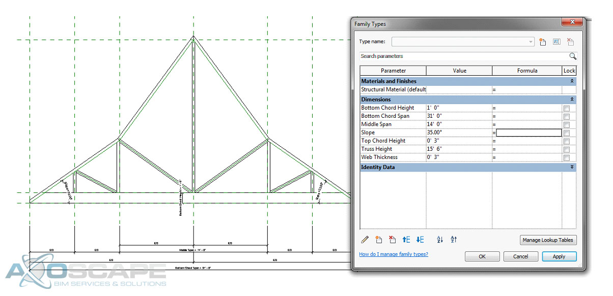
 ⦁ Open up the left elevation and create a reference plane for the thickness of the truss and align extrusions to the reference plane. Then test to make sure everything works like its suppose to.
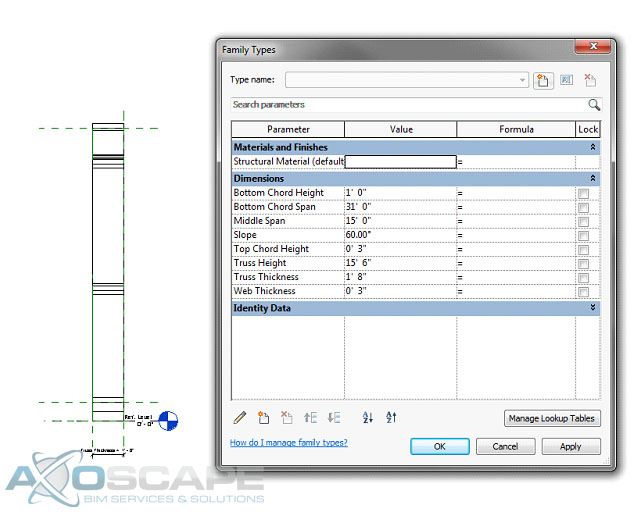


